Functions
2.17 Additional Functions
SIPROTEC, 7SD610, Manual
C53000-G1176-C145-6, Release date 02.2011
246
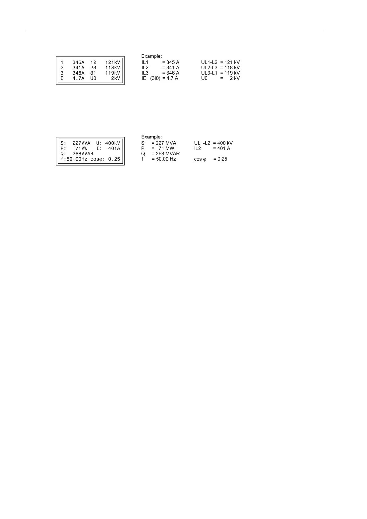
Figure 2-115 Operational measured values in the default display
Default display 3 shows the measured power values and the measured values U
L1-L2
and I
L2
.
Figure 2-116 Operational measured values in the default display
Moreover, the device has several event buffers for operational indications, fault indications, switching statistics,
etc., which are protected against loss of auxiliary supply by means of a backup battery. These indications can
be displayed on the LCD at any time by selection using the keypad or transferred to a personal computer via
the serial service or operator interface. Reading out indications during operation is described in detail in the
SIPROTEC 4 System Description.
After a system fault, for example, important information about the progression of the fault can be retrieved, such
as the pickup of a protection stage or the initiation of a trip signal. The system clock accurately provides the
absolute time when the fault first occurred. The fault progression is output with a relative time referred to the
instant of pickup so that the time until tripping and until reset of the trip command can be recognized. The res-
olution of the time information is 1 ms.
With a PC and the DIGSI protection data processing software, it is also possible to retrieve and display the
events with the convenience of visualisation on a monitor and a menu-guided dialog. The data can either be
printed out or stored elsewhere for later evaluation.
A system fault starts with the detection of the fault by the fault detection of any protection function and ends
with the reset of the fault detection of the last protection function or after the expiry of the auto-reclose reclaim
time, so that several unsuccessful reclose cycles are also stored cohesively. Accordingly a system fault may
contain several individual fault events (from fault detection up to reset of fault detection).
Information to a Control Centre
If the device has a serial system interface, stored information may additionally be transferred via this interface
to a central control and storage device. Transmission is possible via different transmission protocols.
You may test whether the indications are transmitted correctly with DIGSI.
Also the information transmitted to the control centre can be influenced during operation or tests. The IEC
60870-5-103 protocol allows to identify all indications and measured values transferred to the central control
system with an added indication „test mode“ while the device is being tested on site (test mode). This identifi-
cation prevents the indications from being incorrectly interpreted as resulting from an actual power system dis-
turbance or event. Alternatively, you may disable the transmission of indications to the system interface during
tests („Transmission Block“).
To influence information at the system interface during test mode („test mode“ and „transmission block“), a CFC
logic is required. Default settings already include this logic (see Appendix).
The SIPROTEC 4 System Description describes in detail how to activate and deactivate test mode and blocked
data transmission.

 Loading...


