Mounting and Commissioning
3.3 Commissioning
SIPROTEC, 7SD610, Manual
C53000-G1176-C145-6, Release date 02.2011
307
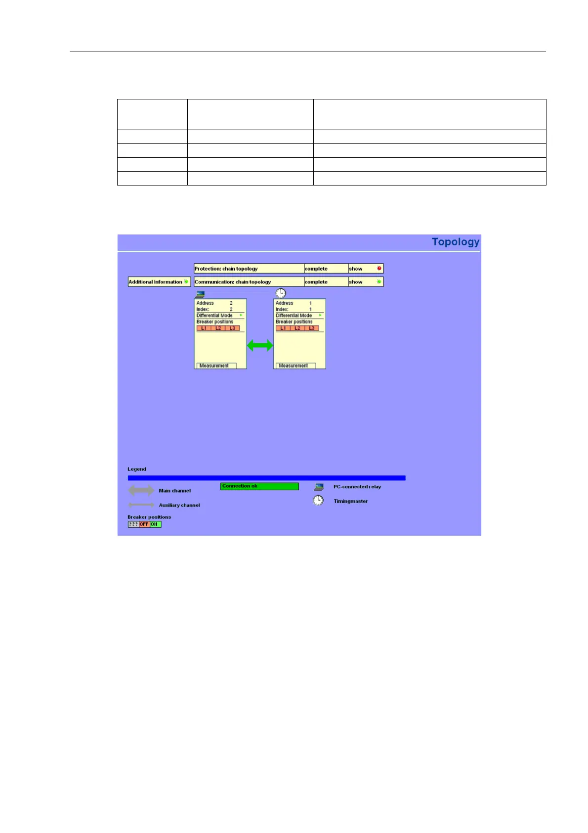
Table 3-16 Connection status
The following figure shows a topology example with additional information.
Figure 3-22 Communication topology – Additional representation
Figure 3-23 shows an example of the protection data interface statistics of the device. The values for the trans-
fer times and the availability are displayed. Both RX and TX direction of the transmission delay times are dis-
played, symmetric conditions are assumed if there is no GPS synchronisation. In this case, the values dis-
played for the transfer time are identical.
Status Colour of the
connection display
Remark
OK green The connection is OK.
failed is not displayed
asynchronous red The connection cannot be used for protective functions.
unknown grey

 Loading...


