Mounting and Commissioning
3.3 Commissioning
SIPROTEC, 7SD610, Manual
C53000-G1176-C145-6, Release date 02.2011
316
If the current flows towards the protected object according to the circuit in Figure 3-27, the currents I
L2
and I
L3
are virtually zero. An earth current 3I
0
of the approximately same level as I
L1
occurs. Accordingly, the voltage
U
L1E
is missing and a zero sequence voltage 3U
0
appears.
In the event of a polarity fault, 3I
0
is in opposite phase withI
L1
or the zero voltage 3U
0
supplements the other
two voltages to a voltage star. Open the circuit breakers, short-circuit current transformers, set current and
voltage transformer connections right and repeat the check.
Note
If parameters were changed for this test, they must be returned to their original state after completion of the test!
Measuring the differential and restraint currents
The test for two ends is terminated with the reading of the differential, restraint and load currents. It is simulta-
neously checked that the current transformer connections have been correctly restored after the I
4
test (if per-
formed).
• Read out the differential, restraint and load currents. They are available for every phase on the device
display or in DIGSI in the measured values.
– The differential currents must be low, at least one scale less than the currents flowing through. If high
charging currents are to be expected in long overhead lines or cables, these are additionally included in
the differential currents.
– The maximum values of the read measured values for the charging current (3 values) are converted to
Ampere and entered in I-DIFF>. The recommended setting for the pickup threshold is 1 · I
cN
.
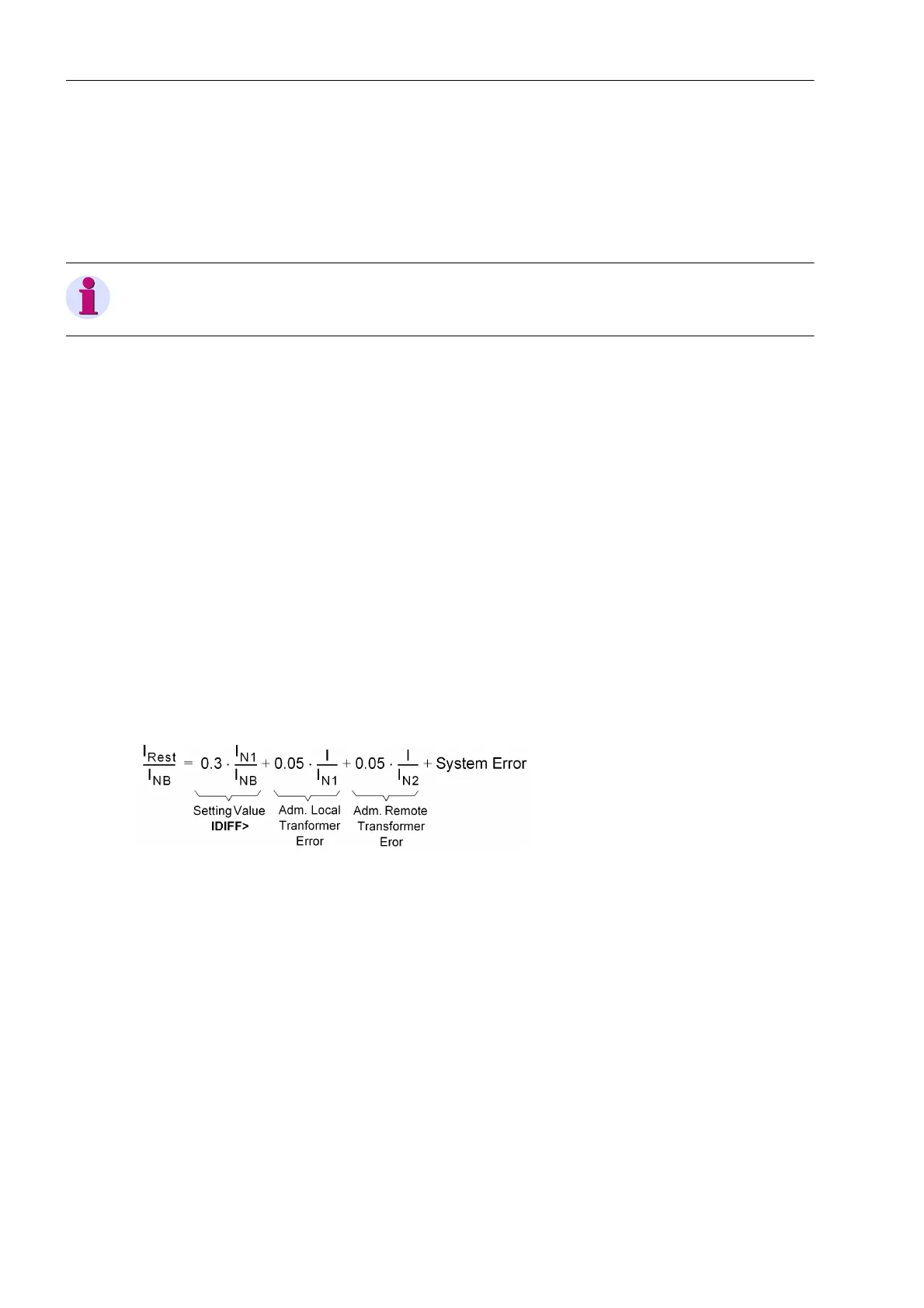
– The restraint currents result from the pickup value I-DIFF> (address 1210, see Section 2.3.2) plus the
sum of the fault currents to be tolerated: Such as the locally permissible current transformer errors ac-
cording to address 253 E% ALF/ALF_N (see Section 2.1.2), the permissible current transformer errors
at the other ends according to the respective setting, as well as the internal estimation of the system
errors (frequency, synchronisation and delay time difference errors). With the default values for I-DIFF>
(0.3 I
N
) and E% ALF/ALF_N (5.0 % = 0.05) the following ensues:
With
I the actually flowing current,
I
NB
the rated operational current (as parameterised),
I
N1
the primary nominal current of the local current transformers,
I
N2
the primary nominal current of the current transformers of the remote end.
In the „WEB-Monitor“ the differential and restraint currents are graphically displayed in a characteristics dia-
gram. An example is shown in Figure 3-28.

 Loading...


