Mounting and Commissioning
3.1 Mounting and Connections
SIPROTEC, 7SD5, Manual
C53000-G1176-C169-5, Release date 02.2011
508
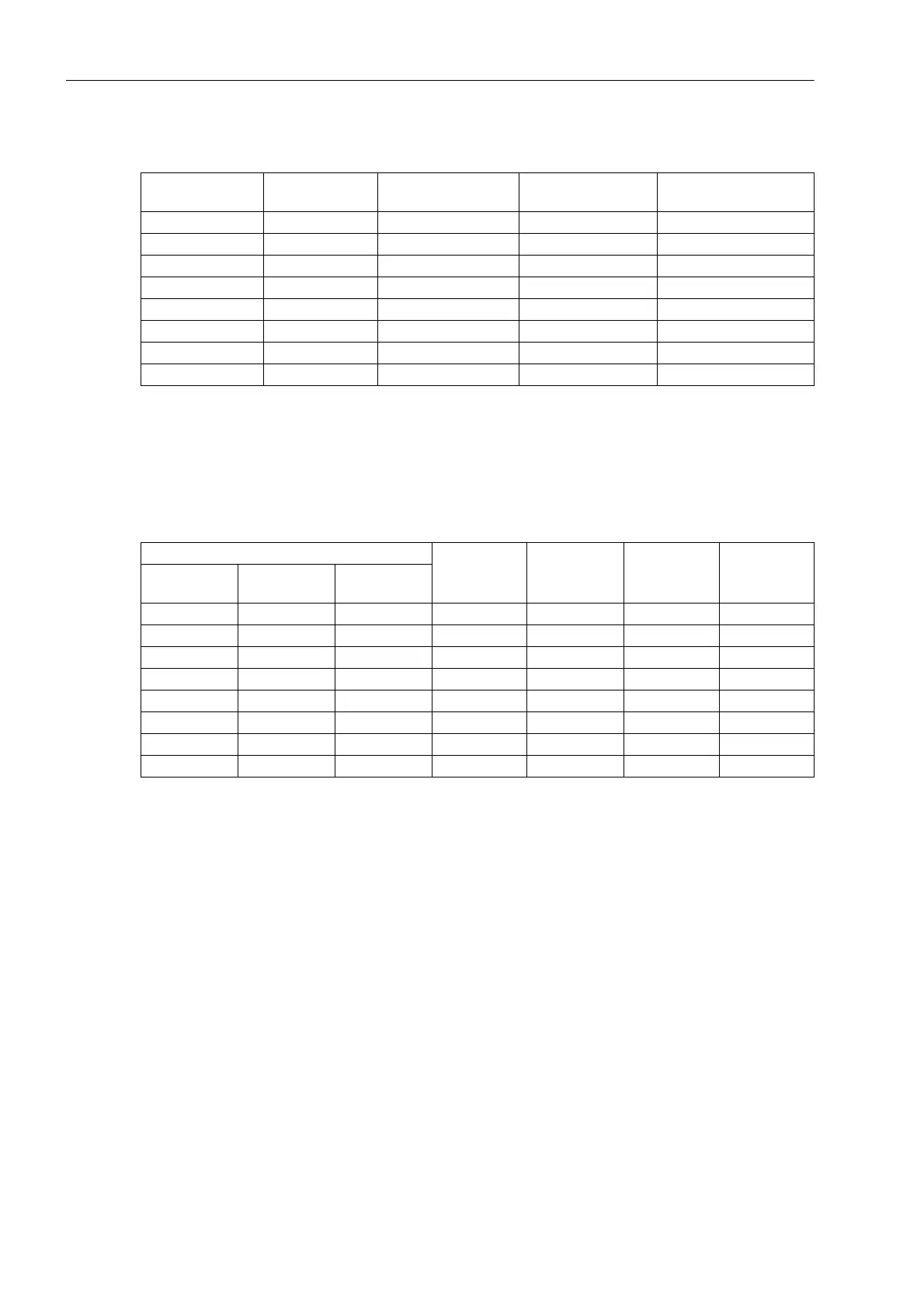
Table 3-5 Jumper settings of the control voltages of the binary inputs BI1 to BI8 on the input/output
module C-I/O-1 with housing size
1
/
2
1)
Factory settings for devices with rated supply voltages of DC 24 V to 125 V
2)
Factory settings for devices with rated supply voltages of DC 110 V to 250 V and AC 115 V
3)
Factory settings for devices with rated supply voltages of DC 220 V to 250 V and AC 115 V
Table 3-6 Jumper setting of the control voltages of the binary inputs BI1 to BI24 on the input/output
module C-I/O-1 for housing size
1
/
1
1)
Factory settings for devices with rated supply voltages of DC 24 V to 125 V
2)
Factory settings for devices with rated supply voltages of DC 110 V to 250 V and AC 115 V
3)
Factory settings for devices with rated supply voltages of DC 220 V to 250 V and AC 115 V
Two different releases of the input/output module CI/O-10 are available. Figure 3-6 shows the layout of the
printed circuit board for devices up to release 7SD5 .../EE, figure 3-7 depicts the printed circuit board layout for
devices 7SD5 .../FF.
Binary inputs slot
19
Jumper Threshold 17 V
1)
Threshold 73 V
2)
Threshold 154 V
3)
BI1 X21/X22 L M H
BI2 X23/X24 L M H
BI3 X25/X26 L M H
BI4 X27/X28 L M H
BI5 X29/X30 L M H
BI6 X31/X32 L M H
BI7 X33/X34 L M H
BI8 X35/X36 L M H
Binary inputs Jumper Threshold 17
V
1)
Threshold 73
V
2)
Threshold
154 V
3)
Slot 33 left
side
Slot 19 right
side
Slot 19 left
side
BI1 BI9 BI17 X21/X22 L M H
BI2 BI10 BI18 X23/X24 L M H
BI3 BI11 BI19 X25/X26 L M H
BI4 BI12 BI20 X27/X28 L M H
BI5 BI13 BI21 X29/X30 L M H
BI6 BI14 BI22 X31/X32 L M H
BI7 BI15 BI23 X33/X34 L M H
BI8 BI16 BI24 X35/X36 L M H
 Loading...


