Mounting and Commissioning
3.1 Mounting and Connections
SIPROTEC, 7SD5, Manual
C53000-G1176-C169-5, Release date 02.2011
507
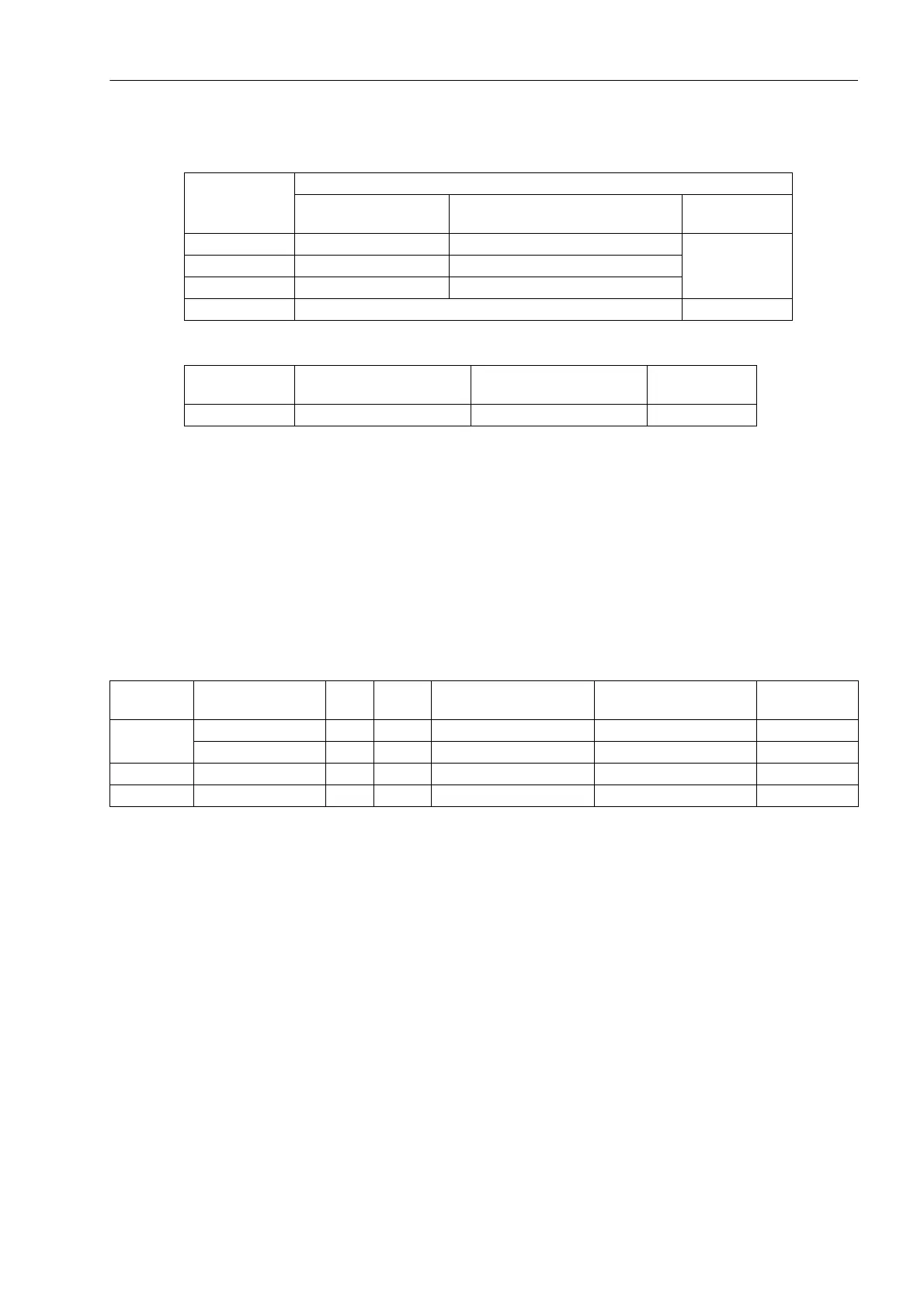
Table 3-2 Jumper settings for the nominal voltage of the integrated power supply on the C-I/O-1
input/output board
Table 3-3 Jumper settings of the Life Contact on the input/output board C-I/O-1
Depending on the device version, the contacts of some binary outputs can be changed from normally open to
normally closed (see General Diagrams in Section A.2)
• In versions 7SD5***-*D/H/M (housing size
1
/
1
with 32 binary outputs) this is valid for the binary outputs BO16
and BO24 (Figure 3-4, slot 19 left and right);
• In versions 7SD5***-*C/G/L (housing size
1
/
1
with 24 binary outputs) this is valid for the binary output BO16
(Figure 3-4, slot 19 right);
• In versions 7SD5***-*P/R/T (housing size
1
/
1
with 32 binary outputs and command acceleration) this is valid
for the binary output BO24 (Figure 3-4, slot 19 left).
Table 3-4 shows the jumper settings for the contact mode.
Table 3-4 Jumper settings for contact mode of the binary outputs BO16 and BO24 on the input/output board C–I/O-1
Checking the control voltages of the binary inputs:
BI1 to BI8 (with housing size
1
/
2
) according to Table 3-5,
BI1 to BI24 (with housing size
1
/
1
depending on version) according to Table 3-7, under margin heading „In-
put/output module C-I/O-10 up to release /EE “
Jumper
Nominal voltage
DC 60 V/110 V/125 V DC 110 V/125 V/220 V/250 V
AC 115 V
DC 24 V/48 V
X51 1-2 2-3 Jumpers X51 to
X53 are not used
X52 1-2 and 3-4 2-3
X53 1-2 2-3
Fuse T2H250V T4H250V
Jumper
Open in Quiescent State
(NO)
Closed in Quiescent State
(NC)
Factory Setting
X40 1-2 2-3 2-3
Device
7SD5***–*
Printed Circuit
Board
For Jumper Open in
Quiescent State (NO)
Closed in
Quiescent State (NC)
Factory
Setting
D/H/M Slot 19 left side BO 16 X40 1-2 2-3 1-2
Slot 19 right side BO 24 X40 1-2 2-3 1-2
C/G/L Slot 19 right side BO 16 X40 1-2 2-3 1-2
P/R/T Slot 19 left side BO 24 X40 1-2 2-3 1-2
 Loading...


