Connection
8.1 Connecting the function modules for direct-on-line start
SIRIUS 3RA28 function modules for mounting on 3RT2 contactors
Manual, 02/2019, A5E03656507620A/RS-AD/005
57
8.1.2 Connecting the solid-state time-delay auxiliary switch
Connection types
The solid-state time-delay auxiliary switch is connected via removable terminals with the
following connection options:
● Screw-type
● Spring-loaded
Connection
You will find information about connection of the screw-type and spring-loaded terminals in
the "appendix" under "Manuals - SIRIUS Modular System (Page 74)" and in the "SIRIUS-
System Overview" manual.
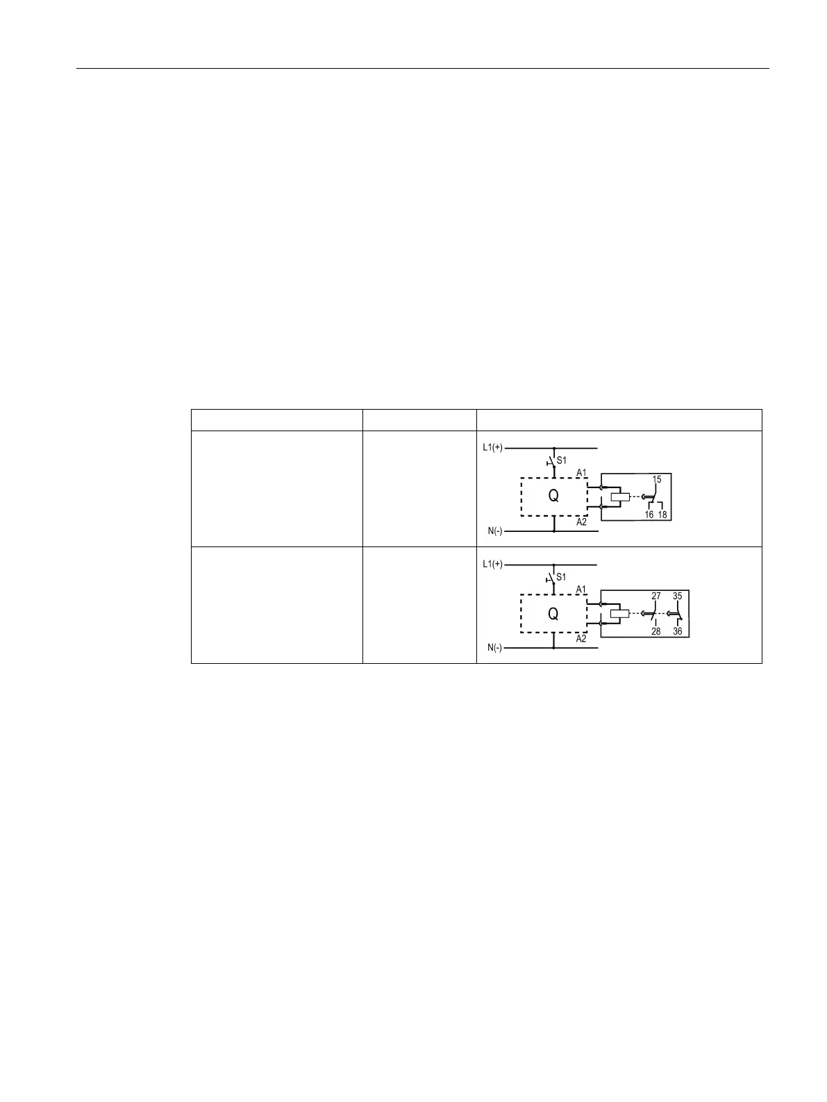
3RA2813-.AW10
ON-delay, 1 CO contact
18 NO
15 NC
16 NC
3RA2813-.FW10
ON-delay, 1 NC con-
tact/1 NO contact
27 NO
28 NO
35 NC
36 NC