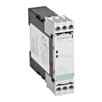
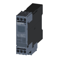
With the setting U
S
= on, the relay switches to the correct state when the supply voltage is applied
but waits to detect the current ow before actually monitoring. The monitoring relay is thus
switched on without generating an error message because, for example. the motor is not yet
running and no current is owing.
With parameterization NC / U
S
= on, a motor can also be switched directly by closing the
monitoring relay if the output relay K1 switches the contactor coil voltage. However, a defect
that prevents current from owing is not signaled with this setting. In this case, setting the relay
switching behavior to NC / I > 3 mA (3UG4621) or NC / I > 50 mA (3UG4622) is appropriate. When
the supply voltage is applied, the output relay K1 is switched to the operate condition and the
ON-delay time (onDel) is started. If current is not yet owing normally after this time has
elapsed, the output relay will switch back to the fault condition.
If a motor is not to be started directly using the monitoring relay, but in parallel using a
pushbutton, with the monitoring relay ensuring the contactor holding, the switching behavior
can be set accordingly.
With the setting I > 3 mA (3UG4621) or I > 50 mA (3UG4622) in combination with a set ON-delay
time onDel = 0, output relay K1 will only switch to the OK condition if a current is actually
measured. In this case, the monitoring relay will hold the contactor until a fault occurs or the
current ow is interrupted by a further button or switch. If an ON-delay time is necessary, initial
switching of the output relay on application of the supply voltage or on starting the ON-delay
time must be suppressed by means of external logic.
Note
The name of the parameter values is based on the assumption that the ON-delay time onDel = 0
is set. The output relay K1 then responds either immediately when the supply voltage U
S
is
applied or after measurement of a current ow on the set NC or NO working principle.
You will nd the switching states of the output relay below in the section entitled "Function
diagrams" and in Chapter "Diagnostics (Page 129)."
3UG4621/3UG4622 current monitoring relays
7.3 Functions
SIRIUS 3UG4 / 3RR2 monitoring relay
124 Equipment Manual, 07/2021, NEB927043002000/RS-AD/005
 Loading...

