① /
②
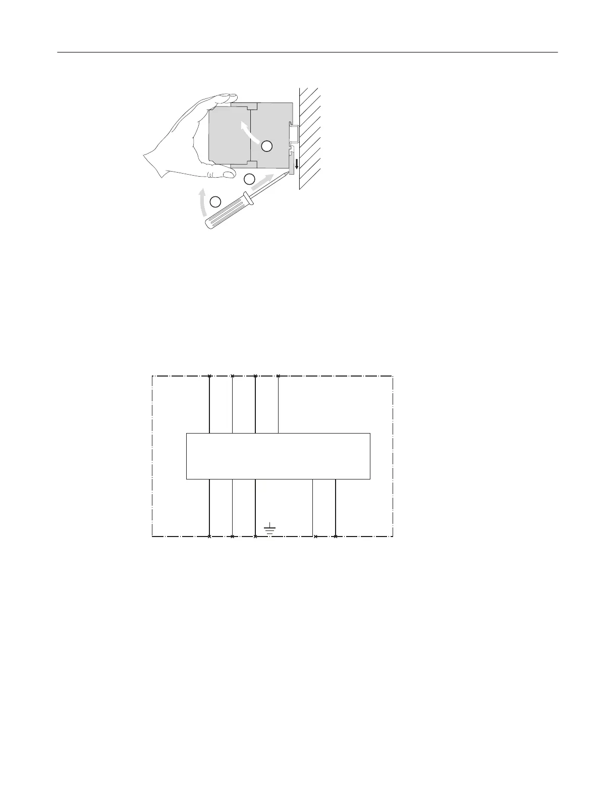
To remove, apply the screwdriver to the device and push it up with a twisting motion against the
tension of the xing spring.
③ Swing the device upwards to remove it.
Figure 13-19 Removing the 3UG4983 voltage reducer module (mounting onto DIN rail)
13.3.2.1 Internal circuit diagrams
Internal circuit diagram 3UG4983-1A / 3UG4983-.AA01
Figure 13-20 3UG4983-1A / 3UG4983-.AA01 insulation monitoring relay
Wiring examples for the 3UG4583 insulation monitoring relay with connected 3UG4983 upstream
module
Measuring inputs L+ and L- can be connected to any conductor. Measuring inputs L+ and L- must
always be connected to dierent conductors.
The rated system voltage is U
n
≤ 690 V AC (15 to 400 Hz) or U
n
≤ 1000 V DC.
Accessories
13.3 Accessories for 3UG458.-1AW30 / 3UG4583-1CW30 insulation monitoring relays
SIRIUS 3UG4 / 3RR2 monitoring relay
Equipment Manual, 07/2021, NEB927043002000/RS-AD/005 269

 Loading...


