You will nd more information about the switching behavior of the output relays in Chapter
"Function (Page 87)".
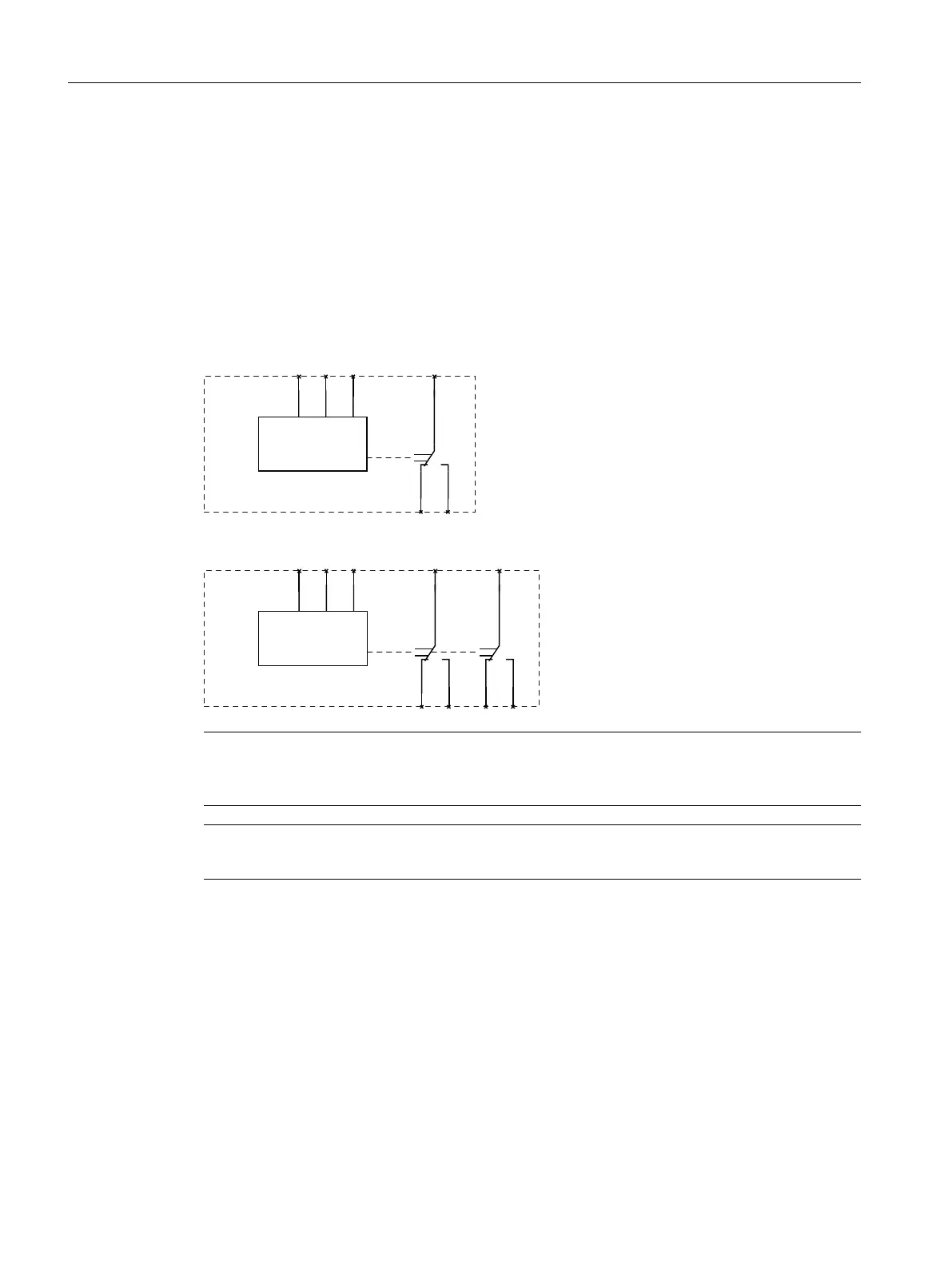
6.3.4 Circuit diagrams
Internal circuit diagrams 3UG4512
3UG4512‑.A.. line monitoring relays
3UG4512‑.B.. line monitoring relays
Note
It is not necessary to fuse the measuring circuit to protect the device. Fusing for line protection
depends on the cross-section used.
Note
The 3UG4512 line monitoring relays are only suitable for line frequencies of 50 / 60 Hz!
3UG4.1 line monitoring relay
6.3 3UG4512 line monitoring relay
SIRIUS 3UG4 / 3RR2 monitoring relay
90 Equipment Manual, 07/2021, NEB927043002000/RS-AD/005

 Loading...


