4.5.4 Diagnostics
Display information
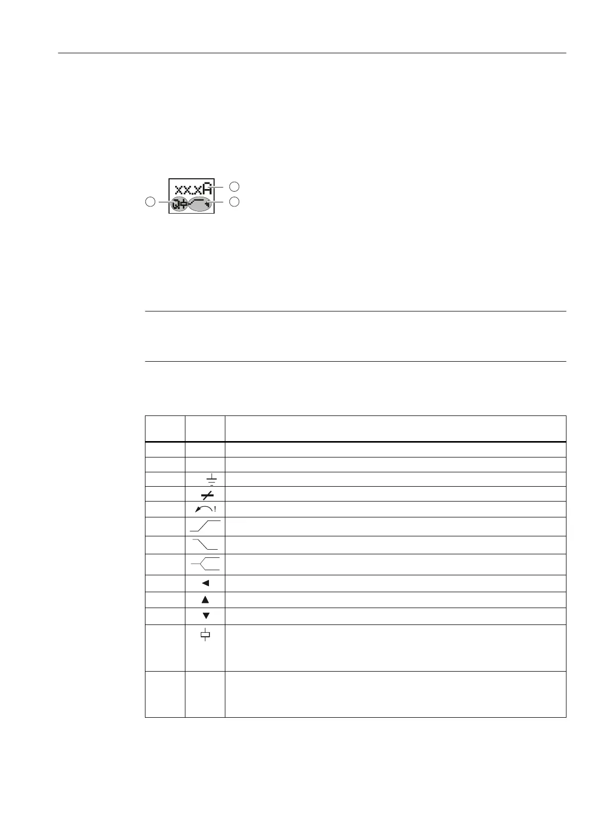
The display is divided into three dierent areas.
① Current measured value or fault symbol
② Type of monitoring
③ Symbols for the semiconductor contact (left) and the CO contact (right)
Meaning of the information on the display
Note
Indications in the event of a fault
The symbols on the display ash to indicate an error.
The following statuses and faults are indicated on the display as a diagnostics message with
ashing symbols:
Display
area
Symbol Meaning
① 12.5A Displays the measured current
① n x I▲ Flashing: Current is above the set blocking current
① I>> Flashing: Fault current detected
① L Flashing: Cable break/phase failure detected
① Flashing: Incorrect phase sequence detected
② Monitoring for current overshoot
② Monitoring for current undershoot
② Range monitoring (monitoring for current overshoot and current undershoot)
② Current is in correct range
② A current overshoot has occurred
② A current undershoot has occurred
③
• Not ashing: Relay contact 31/32 open, relay contact 31/34 closed
• Flashing: Delay time (ON-delay or tripping delay) running
• Masked out: Relay contact 31/32 closed, relay contact 31/34 open
③ Q
• Not ashing: Semiconductor output closed, supply voltage connected
• Flashing: Delay time (ON-delay or tripping delay) running
• Masked out: Semiconductor output open, supply voltage not switched through
3RR2 current monitoring relays
4.5 3RR22 current monitoring relays
SIRIUS 3UG4 / 3RR2 monitoring relay
Equipment Manual, 07/2021, NEB927043002000/RS-AD/005 67

 Loading...


