Figure 13-22 3UG4983-1A / 3UG4983-.AA01 insulation monitoring relay
13.4.1.2 Typical circuit diagrams (3UG4983-.AA01)
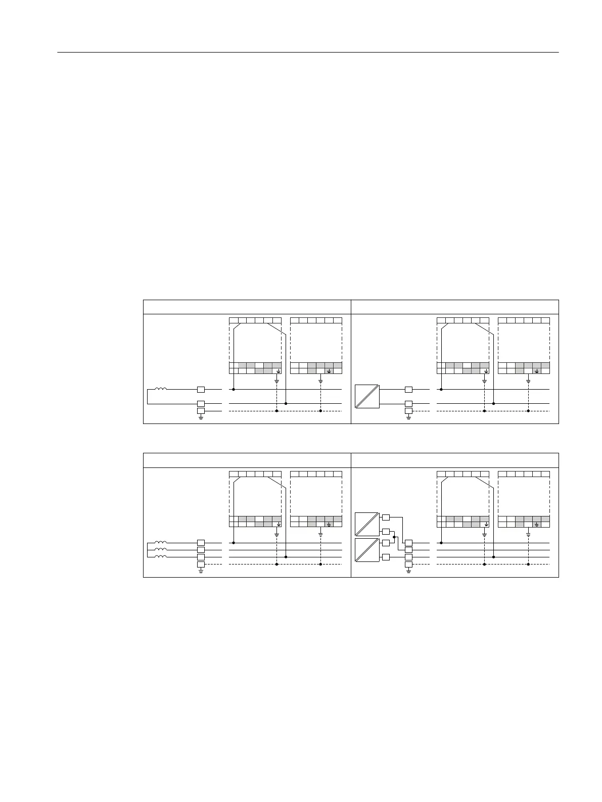
Typical circuit diagrams 3UG4583-.CW31 insulation monitoring relay with
connected 3UG4983-.AA01 voltage reducer module
Measuring inputs L+ and L- can be connected to any conductor. Measuring inputs L+ and L- must
always be connected to dierent conductors.
The rated system voltage is U
n
≤ 690 V AC (15 to 400 Hz) or U
n
≤ 1000 V DC.
2-wire AC system / 2-wire DC system
2-wire AC system 2-wire DC system
/
1
3(
9/
$
<
<
<
/
96
$
9
9
/
.(
9/
9
/
/
9(
9
9
96
3:0
'&
/
/
3(
9/
$
<
<
<
/
96
$
9
9
/
.(
9/
9
/
/
9(
9
9
96
3-wire AC system/3-wire DC system
3-wire AC system 3-wire DC system
/
/
/
3(
$
<
<
<
/
96
$
9
9
/
.(
9/
9/
9
/
/
9(
9
9
96
3:0
3:0
'&
'&
/
/
0
/
/
3(
/
/
$
<
<
<
/
96
$
9
9
/
.(
9/
9/
9
/
/
9(
9
9
96
Accessories
13.4 Accessories for 3UG4583-1CW31 insulation monitoring relays
SIRIUS 3UG4 / 3RR2 monitoring relay
Equipment Manual, 07/2021, NEB927043002000/RS-AD/005 275

 Loading...


