7.6 Circuit diagrams
7.6.1 Internal circuit diagrams
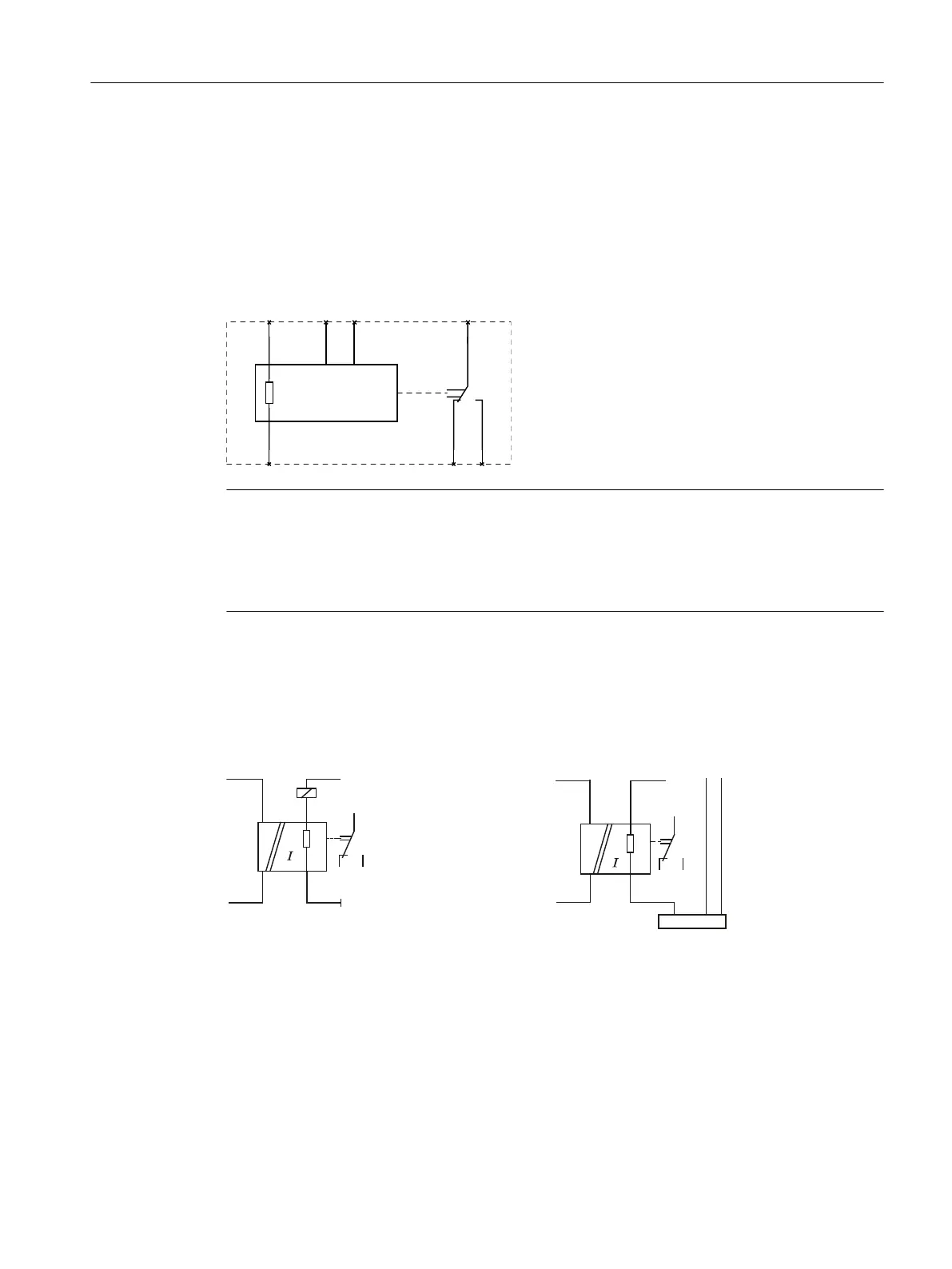
Internal circuit diagrams 3UG4621 / 3UG4622 current monitoring relays
Note
On the 24 V AC / DC version of the 3UG4621/22‑.AA30, terminals A2 and M (GND) are electrically
connected in the device! The load current must ow through terminal M (GND).
On the 24 to 240 V AC/DC versions of the 3UG4621/22‑.AW30, terminals A2 and M (GND) are
electrically separated!
7.6.2 Wiring examples (3UG46..-.AW30)
Single-phase operation Three-phase operation
< >
AC/DC
M
load
Load
U
load
11
14
M
12
A1
A2
IN
3UG462.-.AW30 single-phase operation
< >
AC/DC
Load
A1 IN
A2 M
L3
L2L1
11
1412
3UG462.-.AW30 three-phase operation
3UG4621/3UG4622 current monitoring relays
7.6 Circuit diagrams
SIRIUS 3UG4 / 3RR2 monitoring relay
Equipment Manual, 07/2021, NEB927043002000/RS-AD/005 131

 Loading...


