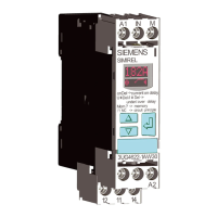
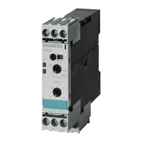
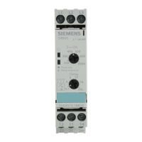
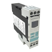
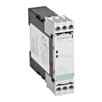
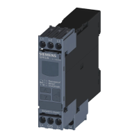
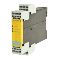
DIP switch
The DIP switches are located behind the label on the front of the 3UG4583 insulation monitoring
relays. Four settings can be parameterized with the DIP switch.
The tables below contain the setting options on the device and the explanations for the relevant
switch positions. When the device is delivered, the switch is in the position OFF.
Table 9-6 DIP switch - 3UG4583
Position 4
Functional principle
3
Open-circuit detection
2
Non-volatile (retentive)
fault storage
1
Functional principle of
output relays K1 and K2
ON ↑ 2 x 1 changeover con‐
tacts
Activated Activated Closed-circuit principle
NC
OFF 1 x 2 changeover contacts Deactivated Deactivated Open-circuit principle NO
Table 9-7 Denitions of the DIP switch positions - 3UG4583
DIP switch ON OFF
Position 4
Functional principle 2 x 1 change‐
over contacts / 1 x 2 changeover
contacts
2 x 1 changeover contacts
If functional principle 2 x 1 changeover con‐
tacts is set, output relay K1 responds to
threshold R1 (shutdown) and output relay
K2 responds to threshold R2 (warning).
1 x 2 changeover contacts
If functional principle 1 x 2 changeover
contacts is set, both output relays K1 and
K2 respond to threshold R1 (warning).
The settings of threshold R2 have no in‐
uence on the principle of operation.
Position 3
Open-circuit detection
Open-circuit detection activated
If open-circuit monitoring is activated, the
insulation monitoring relay monitors cables
connected to terminals L+, L-, and KE for
interruption.
Open-circuit detection deactivated
This setting deactivates open-circuit de‐
tection.
3UG458. insulation monitoring relay.
9.4 3UG4582/3UG4583 insulation monitoring relays
SIRIUS 3UG4 / 3RR2 monitoring relay
Equipment Manual, 07/2021, NEB927043002000/RS-AD/005 189
 Loading...

