Application examples
The gure below shows monitoring for ground fault/insulation fault in the dierent load circuits.
/
/
/
1
3(
0
a
$
<<<
.(
//
$
8*
$:
$
<<<
.(
//
$
8*
$:
① The voltage source is the secondary side of an isolating transformer that galvanically isolates the system and the
downstream circuit.
② The insulation resistance of this motor feeder is always monitored when the motor is switched o. If the motor
contactor drops out, the two NC contacts connect the measuring circuit with the motor cables.
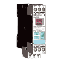
③ The 3UG4582-.AW3. insulation monitoring relay permanently monitors the insulation resistance of the remaining
system with all connected loads.
④ Loads
Figure 9-9 Monitoring for ground fault/insulation fault with dierent load circuits
Note
The maximum cable length of the control cables is 50 m or 100 pF/m.
Wiring examples 3UG4583 insulation monitoring relays
Measuring inputs L+ and L- can be connected to any conductor (phase or N conductor).
Measuring inputs L+ and L- must always be connected to dierent conductors.
The rated line voltage is U
n
≤ 400 V AC (15 to 400 Hz) or U
n
≤ 600 V DC. The 3UG4983-.A voltage
reducer module must be used to monitor systems with higher voltages.
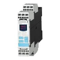
3UG458. insulation monitoring relay.
9.4 3UG4582/3UG4583 insulation monitoring relays
SIRIUS 3UG4 / 3RR2 monitoring relay
194 Equipment Manual, 07/2021, NEB927043002000/RS-AD/005
 Loading...

