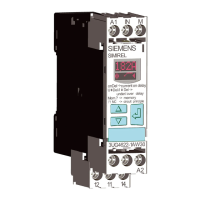
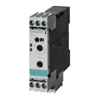
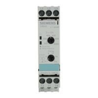
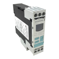
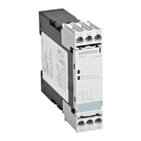
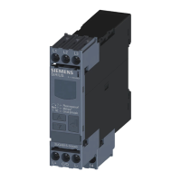
The 3UG4513 line monitoring relay features two rotary buttons for setting the trip delay (Delay)
and the nominal line voltage (U
n
3AC).
The hysteresis is 5 % of the set value of the nominal line voltage.
The 3UG4513 line monitoring relays feature 2 output relays (output relay K1 and output relay
K2). The relays work synchronously.
Note
The specied voltages represent the absolute thresholds.
Monitoring
If the line voltage is switched on, the LED "coil symbol" will light up green. If the correct phase
sequence is applied to terminals L1‑L2‑L3 and if the monitored line-to-line voltage is in the
permissible range of the set nominal line voltage (U
n
3AC), the output relays pick up.
If the phase sequence is incorrect, the "phase failure / phase sequence" LED ashes red and the
output relays remain in their quiescent position.
If the monitored line-to-line voltage falls symmetrically (all three phase voltages at the same
time) or asymmetrically (only one phase voltage) to more than 20 % below the value for the
nominal line voltage set on the front of the device, after the time set on the front has elapsed
(Delay), the output relays will drop out and the "phase failure / phase sequence" LED will light up
red continuously. On a phase failure, the "phase failure / phase sequence" LED lights up red
continuously and the output relays drop out to protect the application from any damage that
may result. The set delay time has no eect on the phase failure monitoring.
Thanks to a special measuring method, a phase failure is detected with certainty despite wide-
range voltage from 160 to 690 V AC and reverse power of up to 80 % from the load in the case
of regenerative power recovery.
You will nd the switching states of the output relays below in section "Function diagrams" and
in Chapter "Diagnostics (Page 95)."
Reset response
The device features an autoreset that resets the output relays to their original state after an error
message and rectication of the fault that has occurred.
Note
The red LED is a fault diagnostics display and does not indicate the current state of the relay!
3UG4.1 line monitoring relay
6.4 3UG4513 line monitoring relay
SIRIUS 3UG4 / 3RR2 monitoring relay
Equipment Manual, 07/2021, NEB927043002000/RS-AD/005 93
 Loading...

