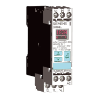
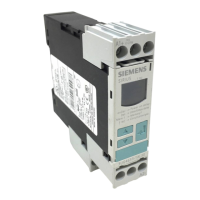
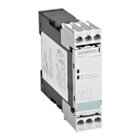
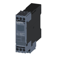
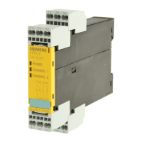
The 3UG4614 line monitoring relays feature 2 output relays (output relay K1 and output relay
K2). The relays work synchronously.
You will nd the setting ranges and factory settings of the available parameters in Chapter
"Operation (Page 99)."
You will nd a description of the individual parameters in Chapter "Parameters (Page 281)."
Note
The specied voltages represent the absolute thresholds.
Monitoring
The output relays respond in accordance with the set relay switching behavior (closed-circuit
principle NC or open-circuit principle NO) if the following conditions are met:
• Correct phase sequence at terminals L1‑L2‑L3
• The monitored voltage (Ux-y) is larger than the set value
• The voltage symmetry (Asy) is smaller than the set value
If a fault occurs (phase failure, incorrect phase sequence, or phase asymmetry), the output
relays switch in accordance with the relay switching behavior.
In the case of incorrect direction of rotation, the 3UG4614 line monitoring relays immediately
shut down. Thanks to a special measuring method, a phase failure is detected with certainty
despite wide-range voltage from 160 to 690 V AC and reverse power of up to 80 % from the load
in the case of regenerative power recovery.
On failure of one of the phases, the output relays drop out immediately to protect the application
from any damage that may result. Set delay times have no eect on the phase failure monitoring.
Note
The 3UG4614 line monitoring relays are only suitable for line frequencies of 50 / 60 Hz!
Startup delay
After applying the supply voltage or resetting the monitoring relays, the set ON-delay begins
(onDel). During this time, undershooting or overshooting of the set threshold values will not
cause the CO contact to respond but instead will result in a restart of the ON-delay.
Tripping delay
If the measured value overshoots or undershoots the set threshold after expiry of the ON-delay
time (onDel), the set tripping delay time (Del) and the relay symbol will ash. After expiry of this
time, the output relays change the switching state. On the display, the current measuring value
and the symbol for undershoot or overshoot ash.
You will nd the switching states of the output relays below in section "Function diagrams" and
in Chapter "Diagnostics (Page 100)."
3UG4.1 line monitoring relay
6.5 3UG4614 line monitoring relay
SIRIUS 3UG4 / 3RR2 monitoring relay
98 Equipment Manual, 07/2021, NEB927043002000/RS-AD/005
 Loading...

