Figure 4 : Principles of Plus
+
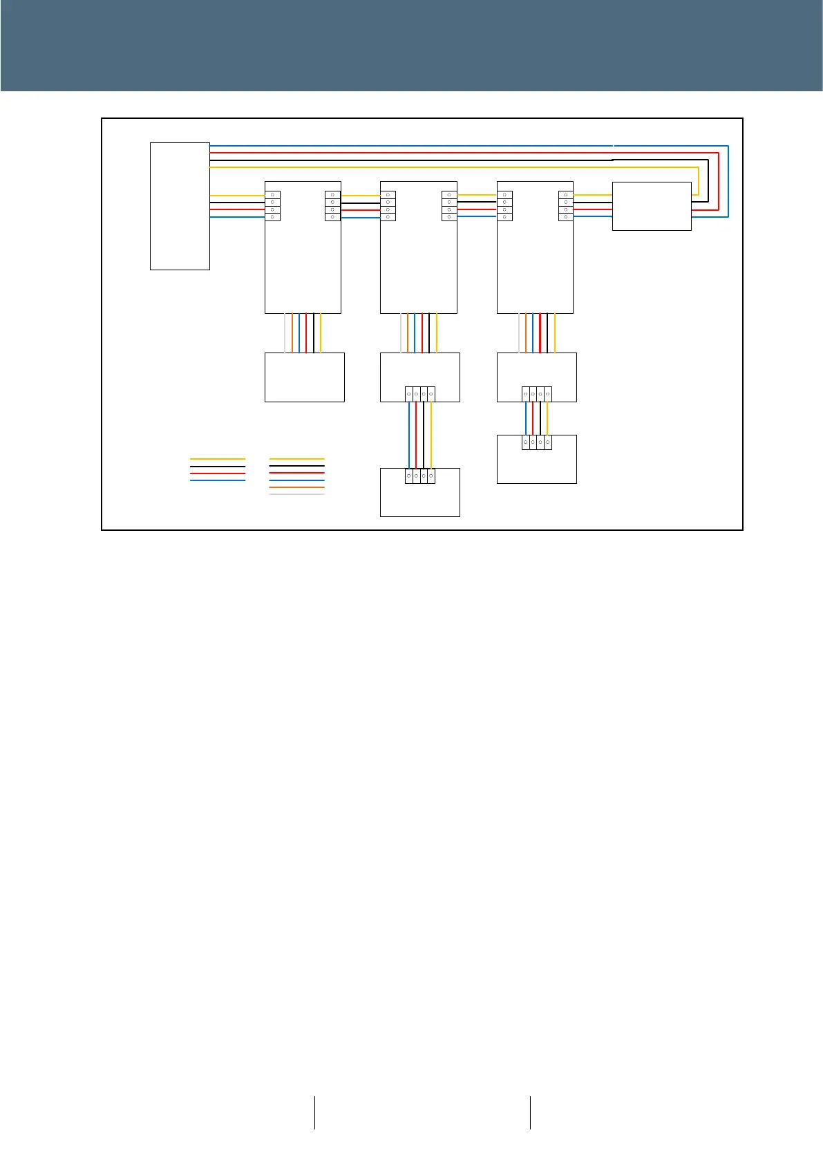
Wiring
The ‘street’ cable is a 2-pair armoured cable. Red and Blue as designated for supply(+48VDC) and
the Yellow and Black are data connections (D+ and D-) respectively.
Connections between the pole top and nodes (RAG or Ped devices) use a six-way dropper cable.
Colour designation is as above with the additional Orange and White (D+ and D- respectively) used
to maintain a data loop from nodes back to the Pole Top Board.
2.2.3 Stub Pole Wiring
The same principles also apply for the Stub Pole. This is treated much like a normal pole whereas
the difference will be that there is no Pole Top Board (PTB). Rather, the street cables are terminated
at the Pedestrian Equipment terminal block and the armouring are terminated using two CT
glands, within the stub pole. There will be an earth link between the two CT glands and a second
earth link that is either terminated on the pole earth stud or then passed through to the Pedestrian
Demand Equipment.