ST950 Plus
+
CPU Card
The CPU card for Plus
+
is common with that used for LV and ELV versions of the ST950. There are
two variants of the CPU card which differ only in the amount of RAM available on the EFC module.
For Plus
+
, only the 128M RAM variant is appropriate.
3.8.1 General
The CPU Card controls the system. It holds the controller configuration and performs the function
of configuration, control and management. The primary external data interfaces are shown in
Figure 19 and detailed in Table 4.
One serial phase bus and two GSPI bus connectors are available on 3 separate RJ45 sockets on the
rear of the CPU Card. The fourth RJ45 socket is reserved for a future GSPI Manual Panel and is
blanked off and should not be used.
The RJ45 socket marked “LSLS” on the ST950 CPU Card is connected to the first position CTB.
The two GSPI interface RJ45 sockets are identical and both marked “SIO”. The first, marked GSPI 1
is connected to the first position CTB. The second can be used for other GSPI peripherals e.g. IO
cards and/or Intelligent Detector Backplanes.
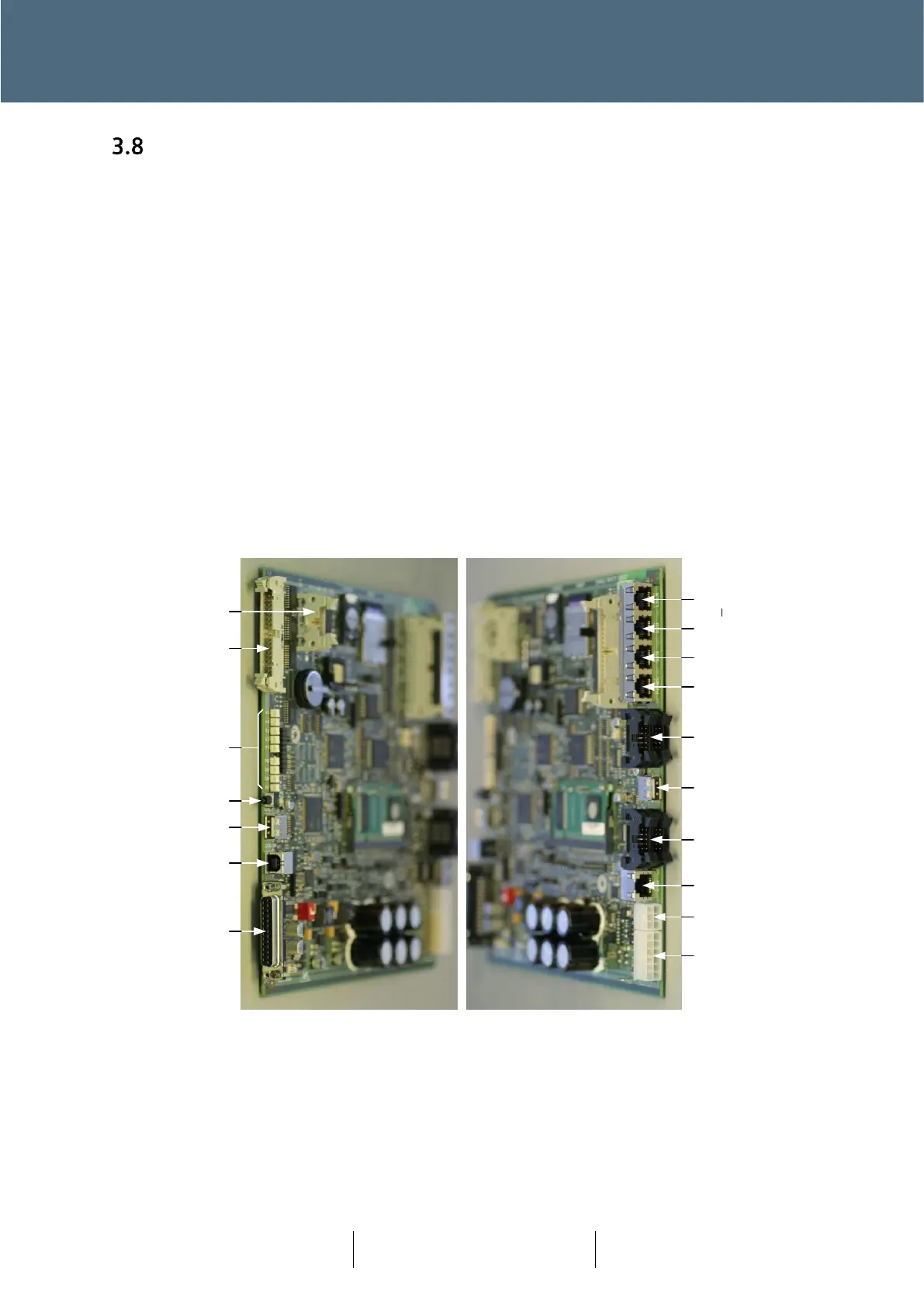
Figure 18 – ST950 Plus
+
CPU Card (front and rear views)
Figure 18 shows the CPU Cards interfaces on the front and rear in the orientation when installed
in the logic rack (but without cables for clarity)
The significant part positions, of the ST950 CPU Card are identified in Figure 19 below and detailed
in Table 4.