Page 93 of 176
667/HE/53000/000
Smartloop
The Smartloop is normally fitted within ‘access chambers’ that are positioned in the most
convenient positions, close to where the inductive loops are to be installed.
The Smartloop provides an interface that allows for further Smartloops to be installed
downstream. The connection(s) is made to PL1on the RAG node, via the terminal block located
with the PTB, see section 4.1.
There are three variants of the Smartloop, to reflect the main ranges of loop inductances that are
normally encountered. However, in most situations it is expected that variant /001 will be the
correct default variant to be selected.
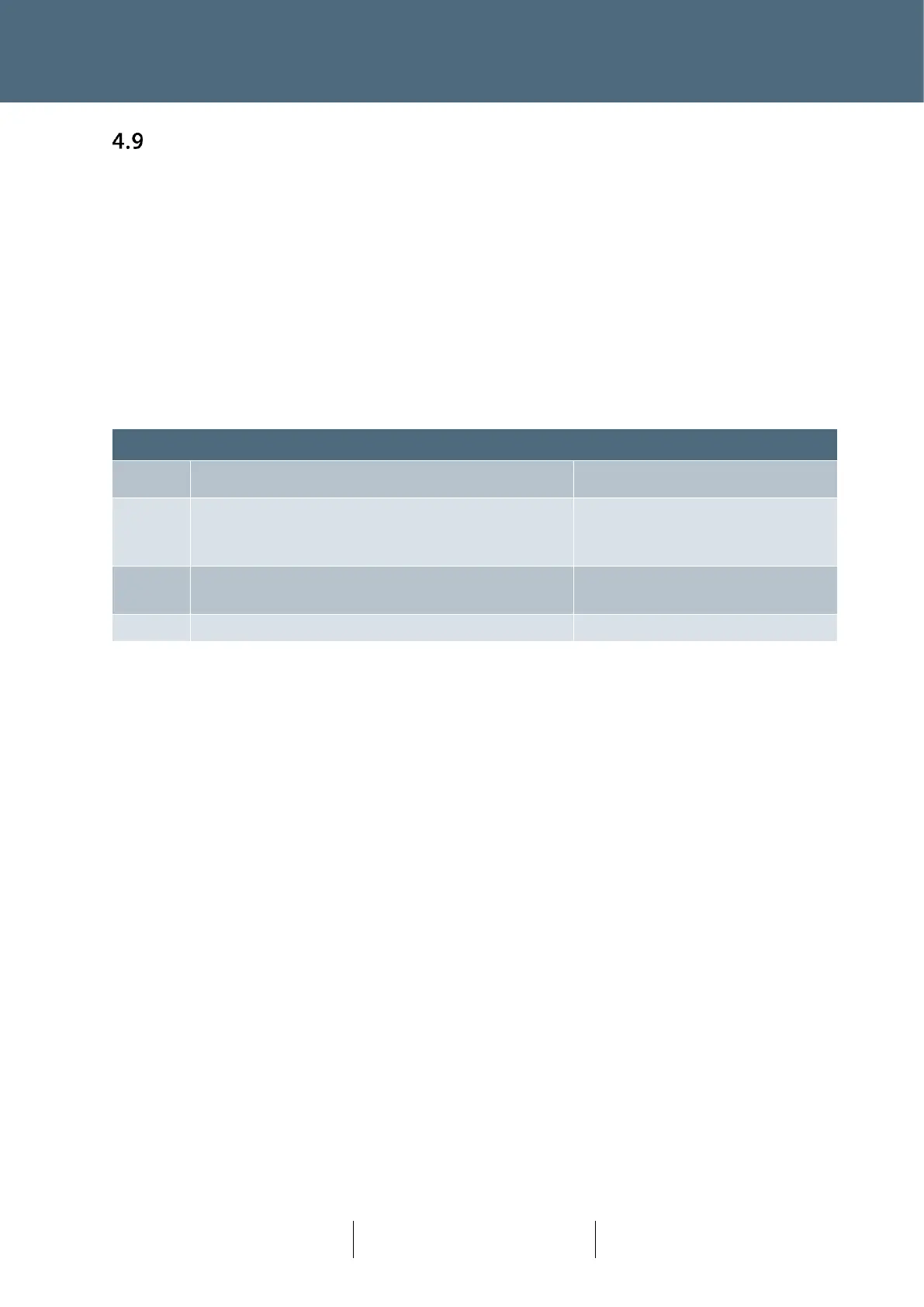
Smartloop Variant Selection Table
Low inductance values and/or short feeder lengths
(this is the usual variant required for most site
installations)
Medium inductance values and/or medium feeder
lengths
High inductance values and/or high feeder lengths
Table 14 : Smartloop Variant Selection Table
Loop feeder length is normally in the range of 0 - 300M but is extendable up to 1000M where the
recommended loop cable core size is 1.5 mm
2
or 2.5 mm
2
.
The following provide a guide for users:
• Short feeder <100m
• Medium feeder 100-300m
• Long feeder >300m
The use of resin (torpedo) joints, or other cable connection methods, should ensure that any loop
feeder/tails or Plus+ network connection can be achieved in a secure and waterproof manner. The
use of other cable connections are also applicable, for example ‘bottle’ joints (but a bottle joint
must be mounted vertically to ensure it remains waterproof).