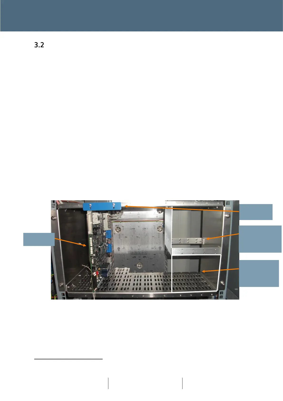
The Controller Rack
Figure 13, below, shows the ST950 Plus
+
controller in a 6U 19" rack. The 19” Controller Rack is
sub-divided into one 6U-high bay and two 3U-high bays. The 6U bay is fitted with the CPU Card.
The arrangement of the rear panel and the rack allows for a number of I/O card or detector options
to be provided:
• 24in 16out rear-panel mounted I/O module - 667/1/46085/001
• 24in 4out rear-panel mounted I/O module - 667/1/46085/002
• Intelligent Detector Backplane - 667/1/32910/950
• ST950 CPU I/O kit 24in 4out - 667/1/46014/000
• WiMag Standard Interface kit - 667/1/47210/100
Where standard loop detectors are required to be installed in the cabinet, the two 3U-high bays
can be fitted with up to two Intelligent Detector Backplanes and the middle 6U section can be
converted to mount a further two IDBs, thereby supporting a total of 16 Loop Detector cards
(each IDB supports up to 4 Loop Detector cards and each Loop Detector card supports up to 4
loops).
If required, a Stratos Outstation unit may be fitted in the bottom right bay, as shown in Figure 13.
The 6U card is held in the rack by a retaining strip at its upper front edge. To release the card,
loosen the clamping screws and move the retaining strip clear of the card guide.
Figure 13 – ST950 Plus
+
19” Rack - Front