3 ST950 PLUS
+
CONTROLLER CABINET
This section details the main elements, of the ST950 Plus
+
system, that are held within the
controller cabinet.
The Primary Plus
+
Controller Cabinet
Figure 12 and Figure 13 below show the ST950 Plus
+
controller CPU card fitted in a standard ST950
Controller Cabinet.
The Master Switch Panel and two CIC cards are all installed on the right-hand side panel of the
cabinet.
The 24V PSU, the 48V PSUs along with the redundancy modules, collectively known as the Power
Bank, a third CIC card and some other miscellaneous equipment are installed on the left hand side
panel of the cabinet. The 48V PSUs for a third CIC are mounted on the bottom of the rear panel.
The 19” Controller Rack is installed in an equipment swing frame at the front of the cabinet; this
frame can be swung open to enable access to the rear of the frame and to the cards and
components installed in the cabinet.
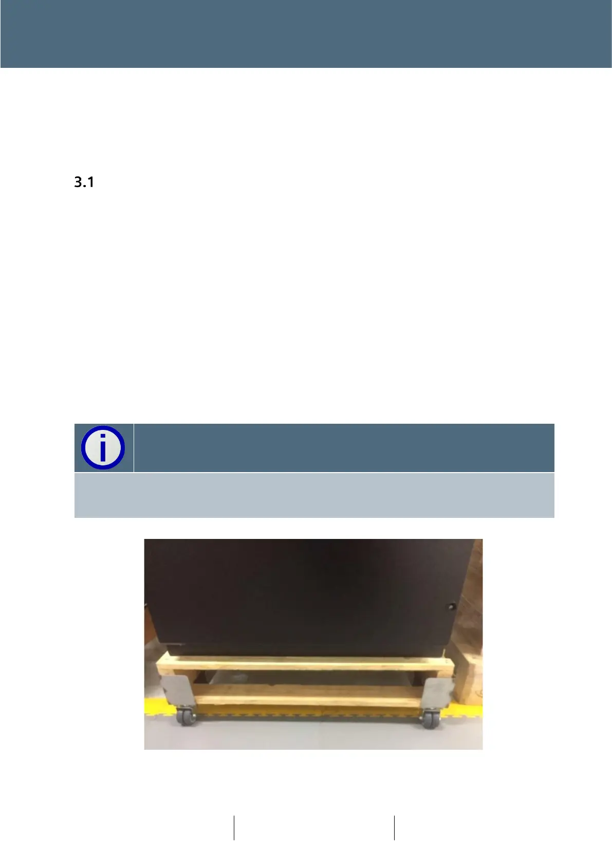
The ST950 Plus
+
controller cabinet is normally supplied on an appropriate pallet. Transport of the
cabinet can be via Pallet truck or using recyclable wheels.
The ST950 Plus+ controller cabinet is not provided with the Cabinet Stool. Several stool types
may be used with ST950 Plus
+
cabinet and must be ordered as a separate item. Reference
section 6.4 for details.