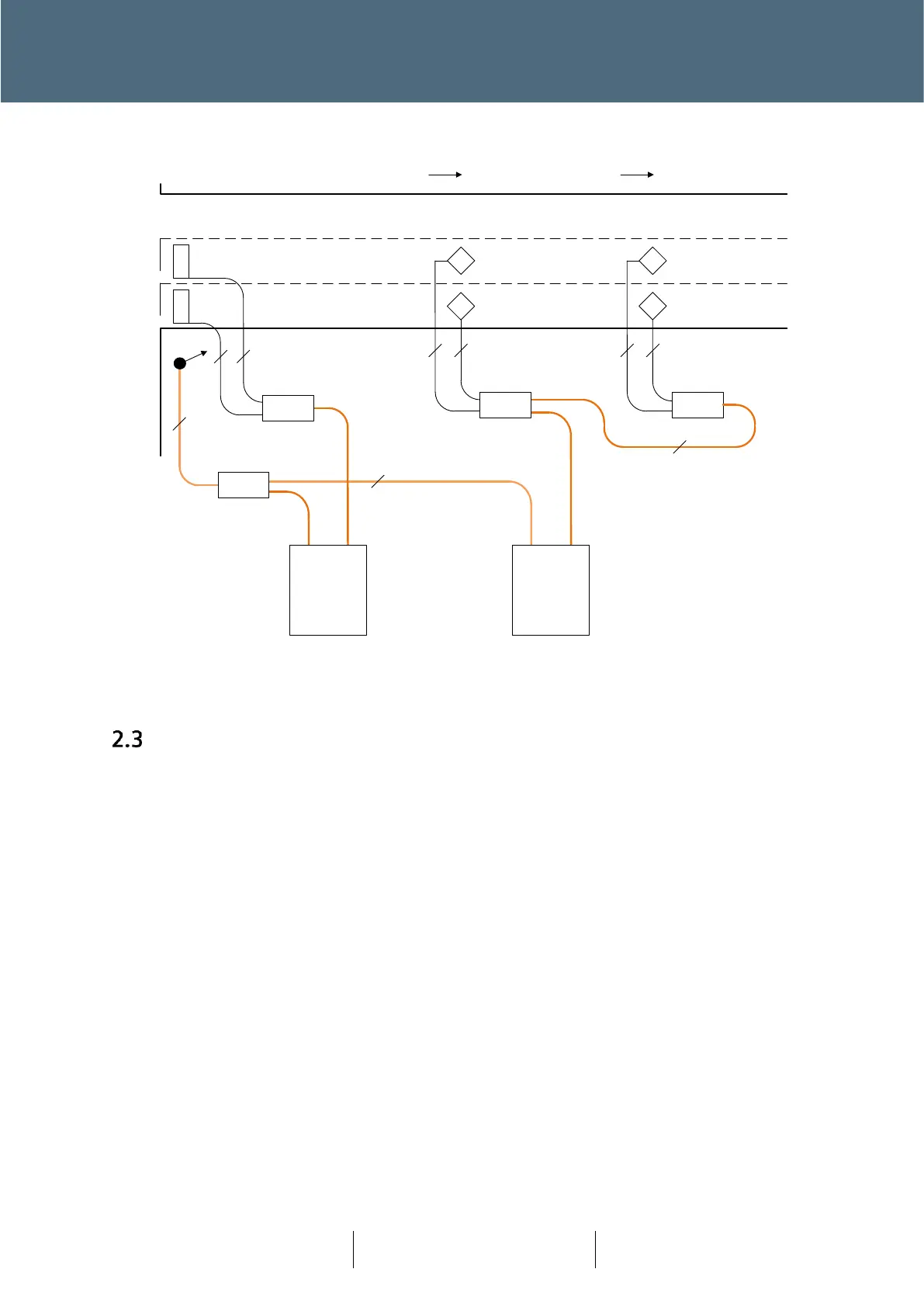
Figure 9 : Smartloop Layout Example 4 : MOVA
Configuration
One of the fundamental changes, that has been brought about by Plus
+
, is that there no longer is
a 1:1 link between outputs from a controller lamp switch card and the individual aspects. This link
is now achieved out on-street, between the Node and the aspect, push button or pedestrian
display unit.
In order to ‘link’ the functional design (IC4) and the on-street equipment a new layer of
configuration is required. It is known as the Plus
+
Design Layout Configuration.
For Plus
+
, the IC4 configuration is fundamentally unchanged, where the traffic junction
configuration (operation) is defined, terms of streams, phases, lamp monitoring and detector
inputs.
The Plus
+
Design Layout Configuration now provides the link between the IC4 configuration and
the junction layout as designed – as opposed to wiring in a Lamp Switch Card.
Siemens Mobility has developed the Plus
+
Design Layout Tool, which works hand in hand with
KeySignals (KeySoft product). KeySignals provides a toolset for Traffic Engineers to design their
junctions within the AutoCAD product suit.