EasyManua.ls Logo

Siemens ST950 Plus+ - Page 22

Siemens ST950 Plus+
178 pages
Print Icon
To Next Page IconTo Next Page
To Previous Page IconTo Previous Page
Loading...
ST950 Plus+ User Manual
Page 22 of 176
667/HE/53000/000
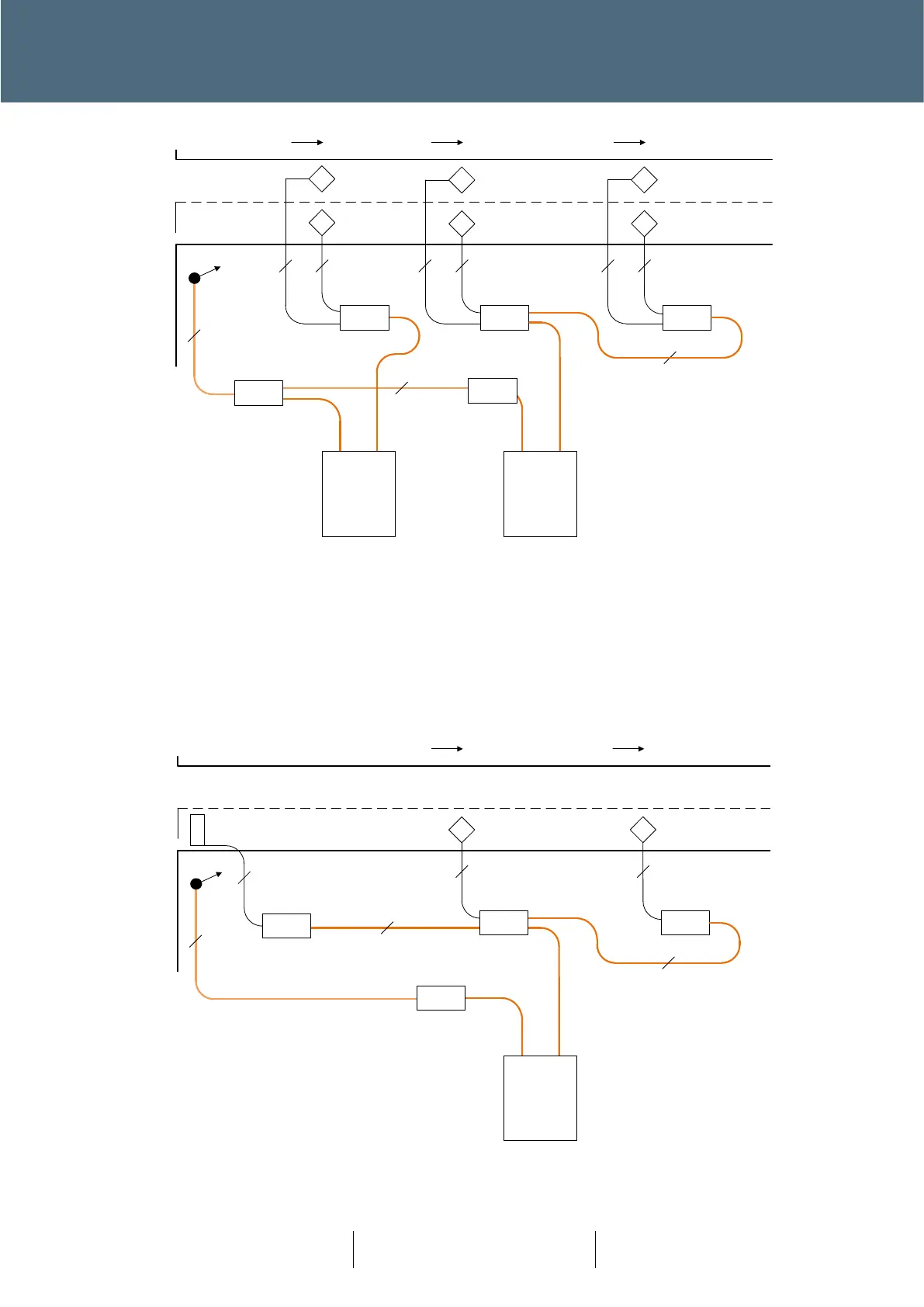
Figure 7 : Smartloop Layout Example 2 : VA
Note: Unlike other Plus+ Nodes the Smartloop has no Bypass Module. In the unlikely event of the
failure of a Smartloop unit, then communications will also be lost to further Smartloops connected
downstream. Smartloops are connected to the Plus+ network via the Spur Connection (PL1) of a
Plus+ RAG Node, and so failure of the RAG Node that provides the Spur connection also results in
the failure to communicate with all the devices on that Spur.
Figure 8 : Smartloop Layout Example 3 : MOVA
SmartLoop
Plus+ Loops
Cable
joint
Cable
joint
Cable
joint
Loop Feeder
2 2 2
4
4
Cable
Joint
22
2
SmartLoop
Plus+ Loops
12m
25m 39m
Z
Y
X
Z
Y
X
Plus+ Street Cable
From RAG Node
Plus+ Street Cable
From upstream
Smartloop
4
Cable
joint
Plus+ Street Cable
from RAG Node
Torpedo
joint
Torpedo
joint
Loop Feeder
2
2 2
2
4
Torpedo
joint
45m 100m
S
L
SmartLoop
Plus+ Loops
Loop Feeder
2
Torpedo
joint
X
IN

Table of Contents

Related product manuals