Page 38 of 176
667/HE/53000/000
GSPI Bus to I/O Cards (SIO) or other GSPI
peripherals
GSPI Manual Panel (PANEL) [Future Use]
Cabinet Signals (Top)
Auxiliary RS232 Connection (Bottom)
Double stacked 10 way IDC
Refer to Table 2 for pinout
Modem Power / Ancillary I/O (Top)
RS232 Modem Connection (Bottom)
Double stacked 10 way IDC
Refer to Table 3 for pinout
Battery Backup module connector
Power Supply Connector (24VDC PSU)
12 way Molex Mini-Fit Jr.
Serial Phase bus (not used for Plus
+
)
Parallel Phase Bus (not used for Plus
+
)
Parallel Manual Panel Port
Table 4 – Connector Functions and Types
3.8.2 Processor Status LEDs
Overview
The LEDs located on the front of the CPU Card and immediately behind the handset port are used
to convey controller operational states and other information to the user.
Front of the CPU Card
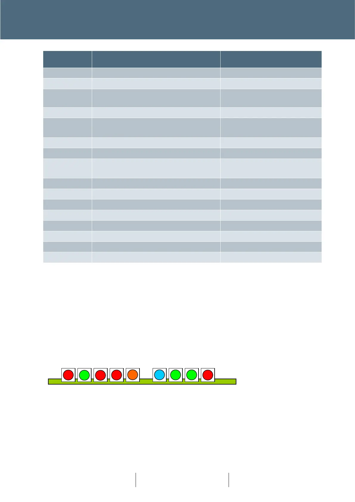
The nine LEDs on the front of the CPU Card as shown below (viewed from the front).
The function of each LED is described below;
WD – Watchdog (red)
Illuminated when the Primary CPU is not running, or an internal fault has been detected.
HB – Heartbeat (green)
WD HB SE SD FF PRG SYS COM BSY