Page 53 of 176
667/HE/53000/000
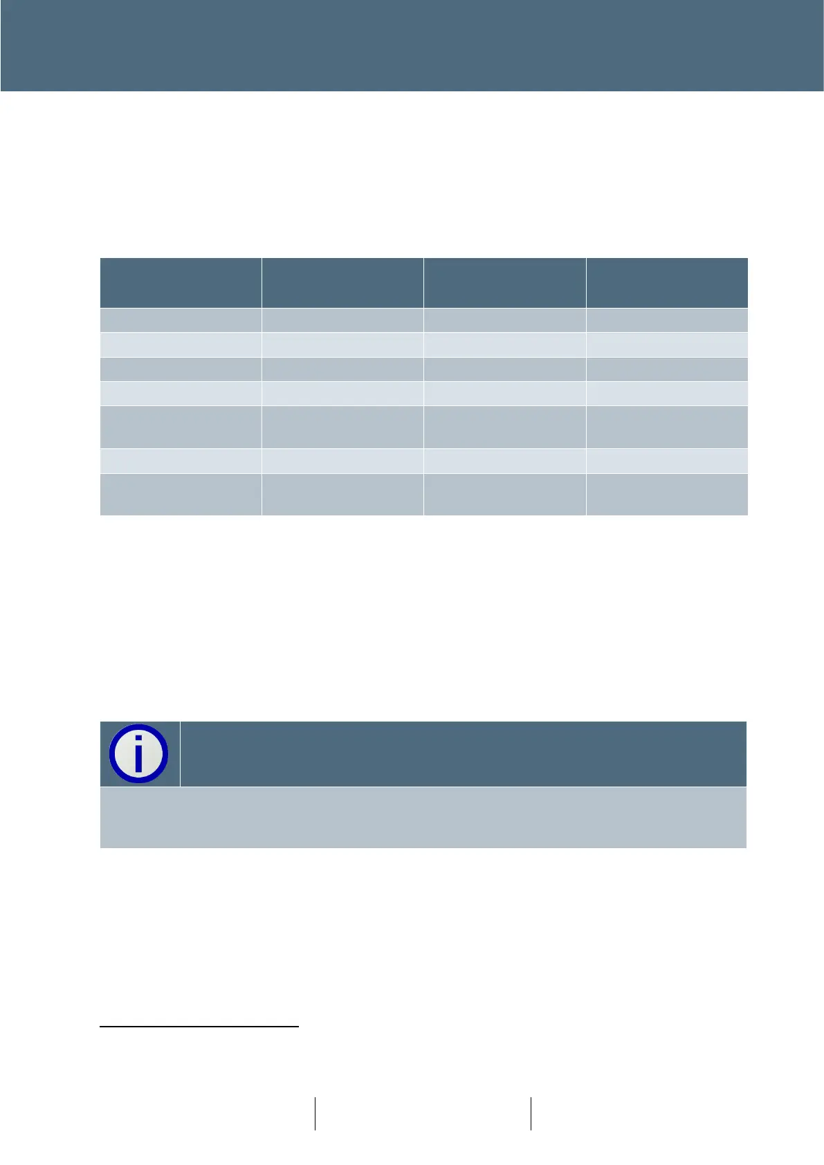
3.14.1 Intelligent Detector Backplane Card LEDs
The Intelligent Detector Backplane Card has three tri-colour status LEDs which are identical to the
LEDs on the I/O card as described in section 3.13 above. It should be noted that these LEDs are
viewed from above and are seen in reverse order (i.e. LP3, LP2 and LP1 from left to right). For this
reason, the table below shows
the LEDs in the order they are seen.
Green Toggle on
Receipt of Message
16
(As above depending
on state)
Table 9 – Intelligent Detector Backplane Card LEDs
3.14.2 Intelligent Detector Backplane Card Rotary Address Switch
This screwdriver-adjustable switch is located on the Intelligent Detector Backplane card(s) as
shown in Figure 26 and is set up for the card address (before the controller is powered up) in
accordance with the appropriate Works Specification. The valid address range is 1 through 9.
Address 0 is the default address switch position for spare cards.
The address range is shared with the IO cards and must be unique. The address range is limited
to 1 to 9. Addresses 10 and above are used by the CTBs. Due to architecture of Plus
+
this is not
expected to be a practical limitation.
Conditions other than those identified above should not occur and can be treated as faults.
May flash so fast that it looks like Green Steady.