4.2.4 Digital I/O (PL2)
The Digital I/O connector is used to interface to a number of peripherals:
• 4 TOPAS 2523 compliant inputs for above ground detectors along with the 0V
returns
• 1 input for Solar Cell – to be used with the ELV Solar Cell
• 3 +24VDC outputs for powering the above ground detectors along with the
respective 0V returns
• 6 pins for the 2 TOPAS 2523 compliant digital outputs (N.O., Common, N.C. on
each of 2 outputs).
• The other pins are used for additional 0V returns and to provide an output for 48V
unswitched (always on)
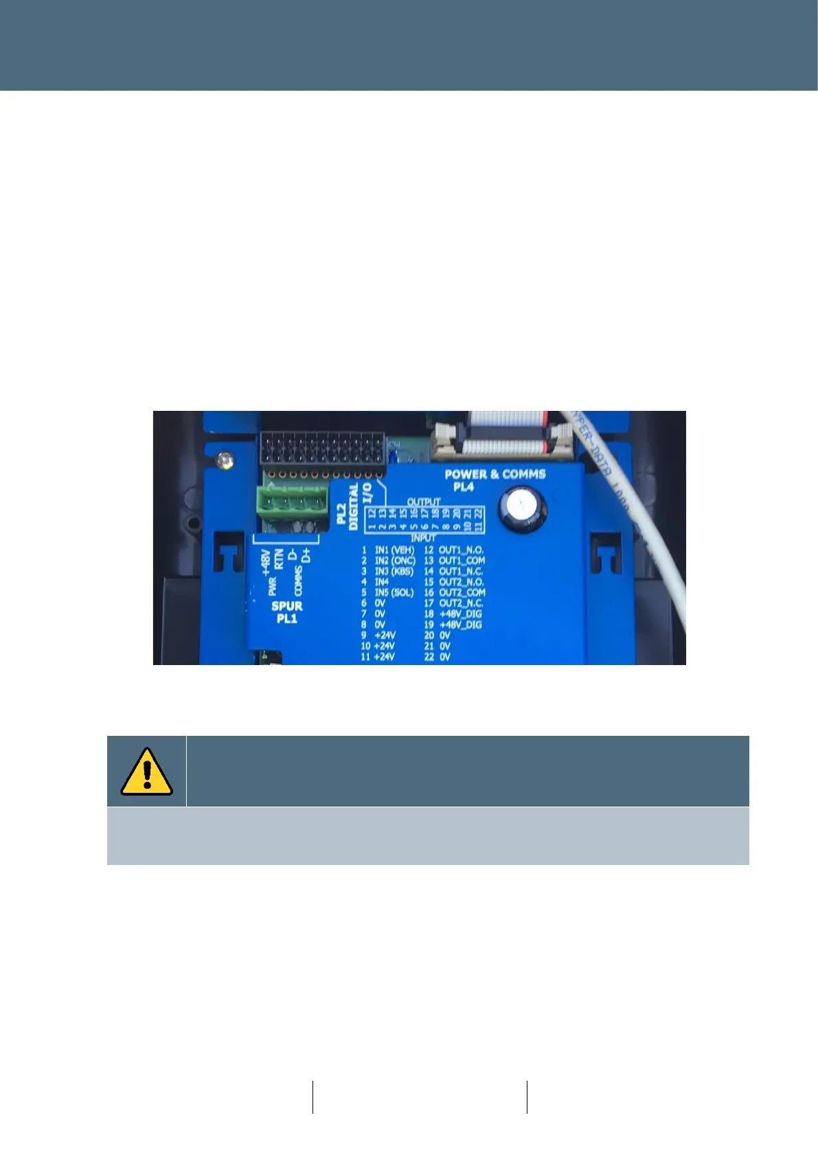
Figure 40 : RAG Node Digital I/O Connector