AP10S
Installation Deutsch
AP10S · Datum 15.04.2020 · Art. Nr. 87100 · Änd. Stand 83/20
9
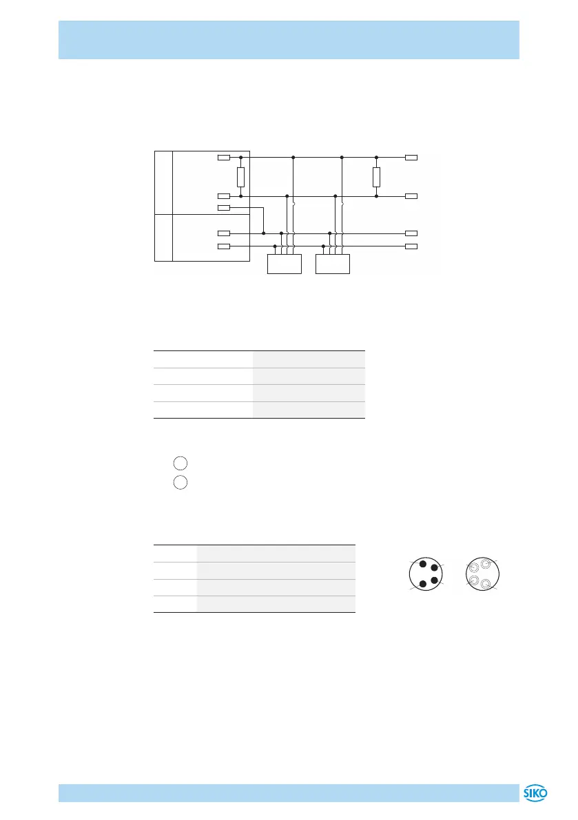
Anschlussschema CAN
Für die Funktion des Feldbusses ist an beiden Busenden je ein Abschluss-
widerstand notwendig (120Ohm). Dieser muss zwischen CANH und CANL
eingesetzt werden.
24 V
24 V
CAN_GND
CANL
CANH
120 R
CANH
CANL
Node 1
120 R
Node n
0 V
0 V
Bus-Master
Versorgung
Abb. 3: Anschlussschema CAN
Datenübertragung Schnittstelle CAN
CAN Baudrate max. Busnetzlänge
125kbit/s 320m
250bit/s 160m
500bit/s 80m
1Mbit/s 25m
Anschlussbelegung
•
1
Bus-IN: Stift 4 pol. M8 (siehe Abb. 4).
•
2
Bus-OUT: Buchse 4 pol. M8 (siehe Abb. 4).
Zubehör Gegenstecker und Kabelverlängerungen siehe Kapitel 8.
PIN Belegung
1 DÜB/CANL
2 DÜA/CANH
3 +UB
4 GND
Ansichtseite = Steckseite
Bus-OUTBus-IN
 Loading...