REKORD Operating manual - English
14 Copyright Silca 2 007
6 MACHINE REGULATION AND UTILIZATION
6.1
Checking and setting
The cutting tool on the REKOR D is the part used to cu t the ke y blan ks and sho uld be period ically
checked and replaced, if necessary.
Every time the cutting tool is changed, and during periodical operational tests, check calibration.
6.2
Calibration
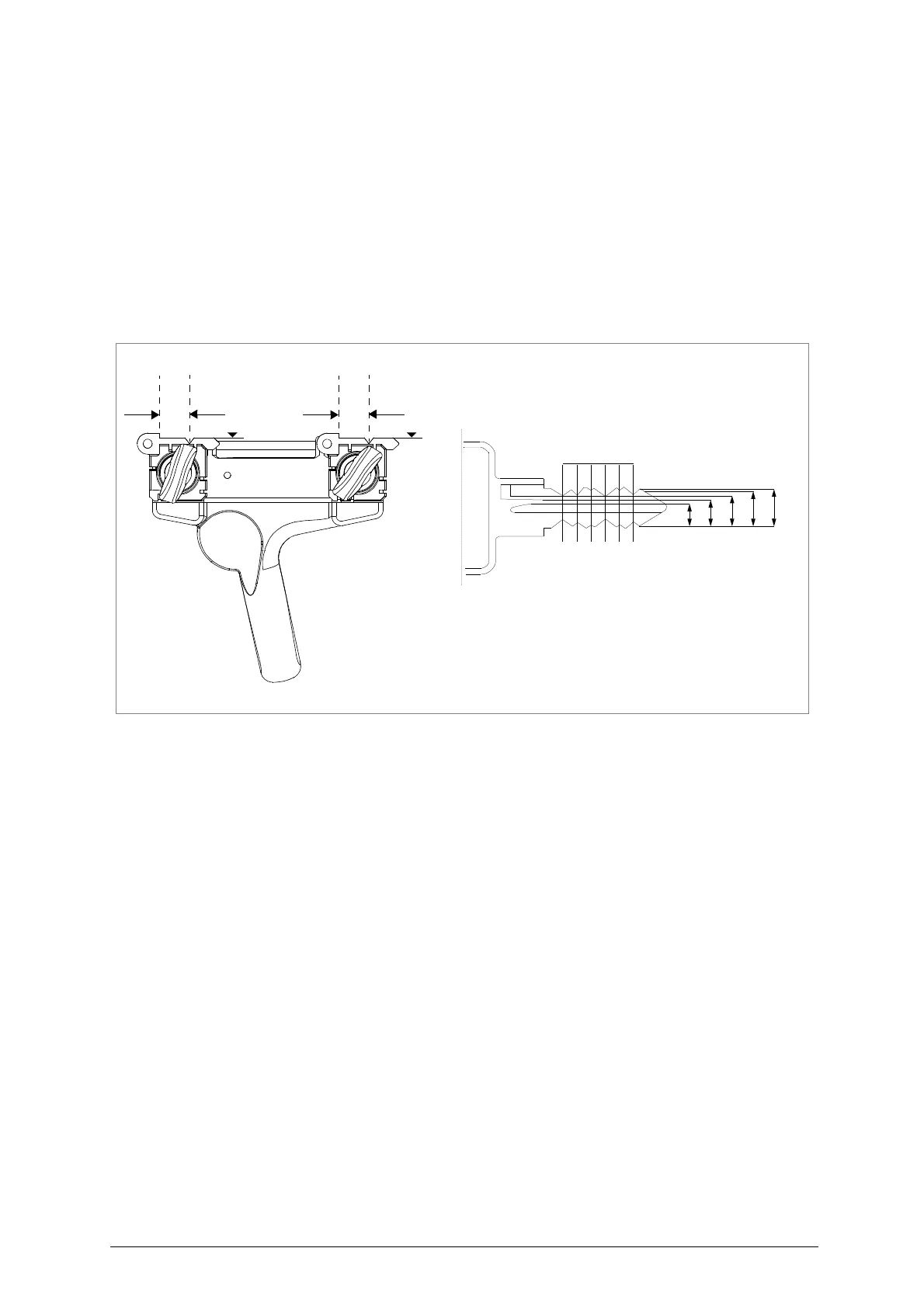
The REKORD key-cutting machine requires two types of calibration: axis and depth.
Axis calibration:
Axis calibration is regulation of the space between the stop and the cuts (fig. 11).
The axis setting for the REKORD is fixed and is established on assembly in our workshops
Fig. 11
Depth calibration:
Depth calibration is regulation of the cutting depth (fig. 11-A).
Proceed as follows:
1)
Ensu
re that the key-cutting
machine is off by unplugging the power cable.
2)
Place the adju
sting keys (provided) on
the clamps (fig. 12-B).
3)
Ch
eck that the adjusting keys adhere properl
y to the clamps (fig. 12-B).
4)
Turn the
gauge rod (G) to
wards the ope
rator so that the gauges come into contact with the adjusting
keys (fig. 12-B). Lower the gauge rod (G).
5) Release the carriage by raising the release lever
(B) (fig. 4).
6)
Ra
ise the
carriage and take up to the cutti
ng tool.
7)
Take the keys into contact with the cutting too
l and tracer point.
8)
Turn the
cutting
tool anticlockwise manually and
check that it skims the adjusting keys in several
places.
9)
If necessary, regul
ate the depth of
the cut with the micrometric tracer point, as follows:
a)
loosen the screw holding the tracer point (J).
b)
turn the grub screw (K) clockwise to advance the tracer point.
c)
turn the grub screw (K) anticlockwise to return.
ATTENTION: each notch on the centesimal ring corresponds to 0,025 mm (fig. 12-A).
10)
Repeat these operations until regulation is complete, then tighten the tracer point locking grub scre
(J).
6
4
8
9
0
cutting
I II III IV V VI
cutting
space
depth
B
A