Operating manual - English Technica EU
22 Copyright Silca 2005
5.10 Motor replacement
ATTENTION:
turn the machine off and unplug it
.
1) Remove the swarf tray (V).
2) Loosen the 3 screws (C2) on the cutter shield and remove (fig. 27, page 18).
3) Remove the 4 screws (V1) on the top cover and remove by lifting it slightly and turning (fig. 26, page 18).
4) Loosen the screw (W2) on the belt cover and remove (pull out towards the front of the machine) (fig. 28, page
18).
5) Place the machine on its back.
6) Loosen the 7 screws (N1) and remove the bottom protective plate (N) (fig. 31, page 20).
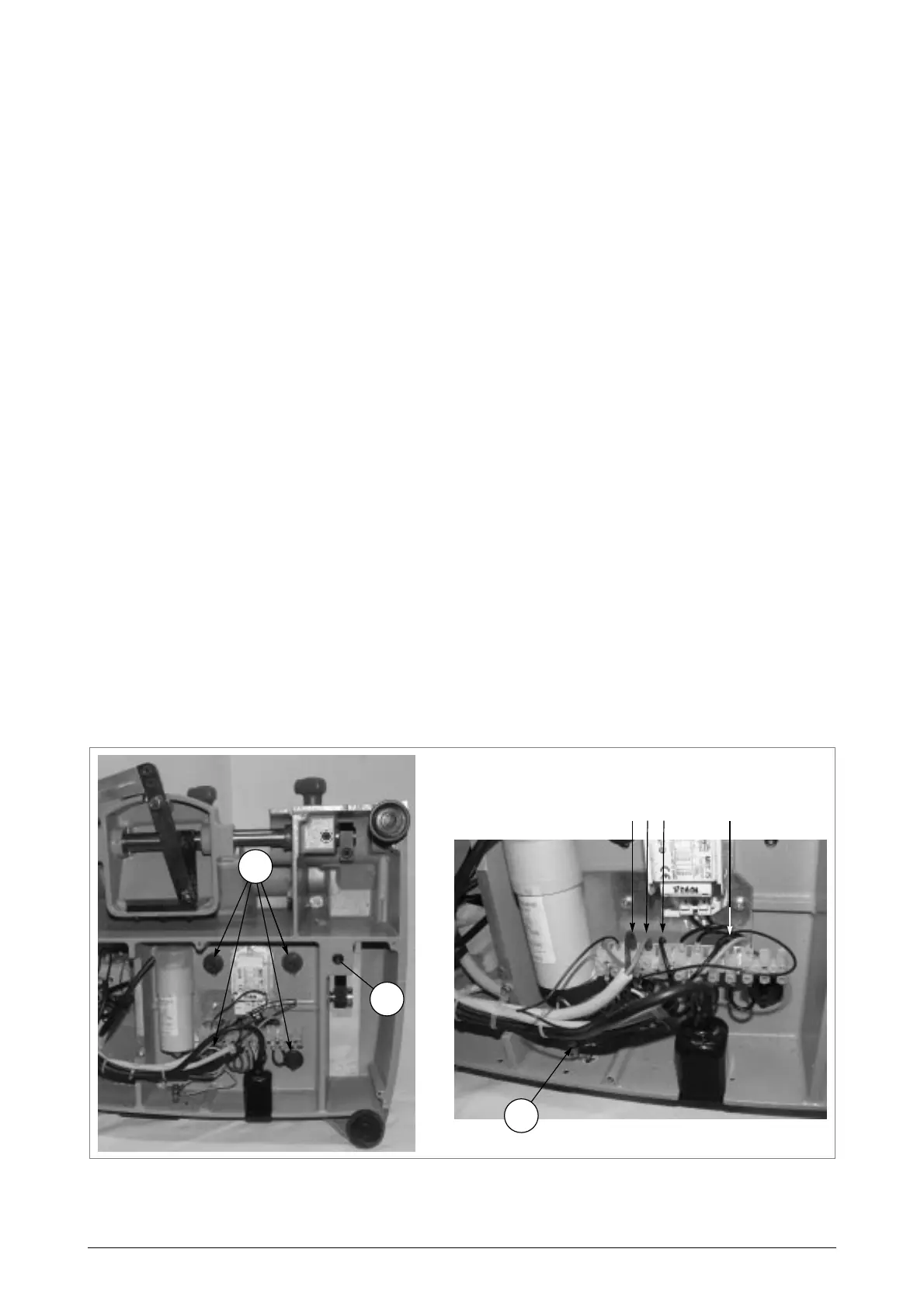
7) Loosen the grub screw (W3) (fig. 37) in order to lower the belt tightening pulley and allow the belt to come off
the motor pulley.
8) Disconnect the 4 wires [3] [4] [5] [9] from the terminal board and the earth wire by loosening the nut (V4).
9) Loosen the 4 fixing nuts (H2) on the motor and remove together with their washers.
10)Place the machine upright on the bench.
11)Pull out the commutator knob (B) and loosen the 2 fixing screws (B2) (fig. 36, page 21).
12)Pull the switch out to the left and, paying attention to their position, disconnect the 6 motor wires from their
connections (fig. 39, page 23).
13)Loosen the 2 grub screws (H1) on the motor pulley (fig. 38). Remove the pulley and fit to the new motor, secure
by tightening the 2 grub screws (H1).
14)Remove the old motor from its seat, together with the 4 screws (H3) (fig. 38, page 23).
15)Fit the new motor into its seat, together with the 4 screws (H3).
16)Fit the belt, first into the motor pulley then (exerting a little pressure) into the main pulley, turning it manually.
17)Place the machine on its back, paying attention to the motor.
18)Tighten (first place the washers in position) the 4 motor fixing nuts (H2) (fig. 37).
19)Tighten the grub screw (W3) until the belt is properly tensioned.
20)Connect the 4 terminal board wires [3] [4] [5] [9] and the earth wire and tighten the nut (V4).
21)Replace the bottom protective plate and secure with the 7 screws (N1).
22)Place the machine upright on the bench.
23)Connect the 6 motor wires to the switch.
24)Push the switch upwards to fit into its seat. Secure with the 2 screws (B3) and replace the knob (B) (fig. 35 and
fig. 36).
25)Replace the belt cover and secure with the screw (W2).
26)Replace the top cover and secure with the 4 screws (V1).
27)Replace the cutter shield and secure with the 3 screws (C2).
28)Replace the swarf tray.
Fig. 37
34 5 9
V4
W3
H2