20
Power
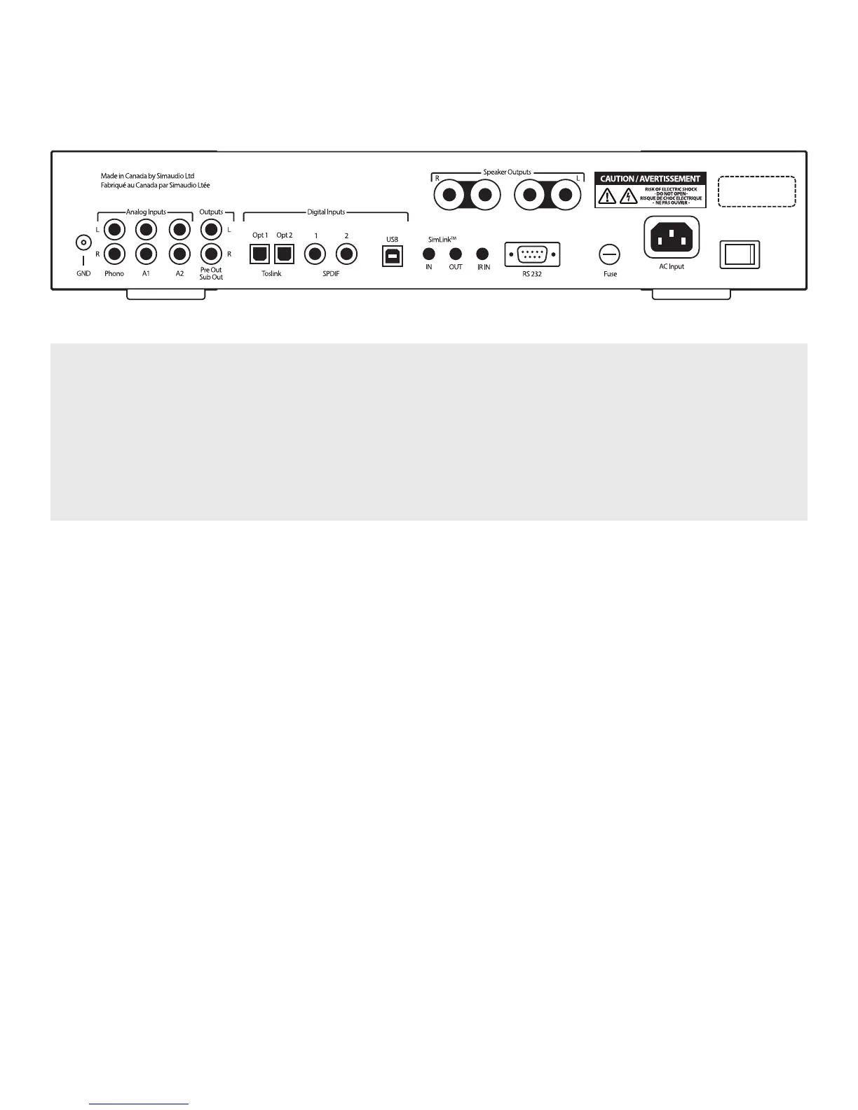
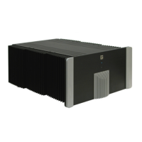
Figure 2: Back panel of the MOON 240i
The rear panel will look similar to Figure 2 (above). On the far left side is a screw labelled “GND” for use with a turntable’s
grounding wire followed by three pairs of “Analog Inputs” on RCA connectors, labelled “L” for Left (white) on the top
row and “R” for Right (red) on the bottom row; The first input “PHONO” is for use with a turntable ONLY; The second and
third inputs “A1” (Analog 1) and “A2” (Analog 2) are reserved for analog source components such as tuner or CD player
with analog outputs. The fourth pair of RCA connectors labelled “OUTPUT” can be used if (i) you have a stand-alone power
amplifier (“PRE OUT”) as opposed to using the 240i’s power amplifier section or (ii) you have a sub-woofer (SUB OUT);
This variable output is controlled by the 240i’s volume level setting.
Rear Panel Connections
Directly to the right of the aforementioned analog
inputs and output you will see the digital inputs.
Two (2) optical inputs using Toslink connectors
labelled “OPT1” and “OPT2” (“OPTICAL 1” and
“OPTICAL 2” in the SETUP); Two (2) SPDIF inputs on
RCA connectors labelled “SPDIF 1” and “SPDIF 2”
(same name in SETUP); These SPDIF inputs will
benet greatly from digital cables with an impedance
of 75 ohm; Next is the “USB” input using a type-B USB
connector (same in SETUP).
Moving further right, the MOON 240i is equipped with
a pair of speaker binding posts, labelled “SPEAKER
OUTPUTS” “R” and “L” for connection to your
loudspeakers. Take care to respect the polarity
(“+” is red , “-” is black) between the binding posts
and the cable connectors on your loudspeakers.
Moving further right, the MOON 240i is equipped
with a pair of speaker binding posts, labelled “SPEAK-
ER OUTPUTS” “R” and “L” for connection to your loud-
speakers. Take care to respect the polarity (“+” is red ,
“-” is black) between the binding posts and the cable
connectors on your loudspeakers.
On the far right side are the “AC Fuse” socket cover,
the IEC receptacle, labeled “AC INPUT” for the included
AC power cord and the main power switch (“0”=o,
“1”=on). Connect the supplied AC power cable
to the IEC receptacle. Ensure that the AC wall outlet
you use has a functioning ground. For the best sonic
performance, it is preferable that you plug your 240i
directly into a dedicated AC outlet and avoid using
an extension cord.
SimLink
TM
This in-house developed protocol provides for
communication between MOON components, allowing
you to control various functions of several components
with the touch of one button.