Smart Machine Smart Decision
SIM7000 _Hardware Design _V1.04 2018-1-31
Table 11: UART electronic characteristic
Symbol Description Min. Typ. Max. Unit
V
UART input high level voltage 1.17 1.8 2.1 V
V
IL
UART input low level voltage -0.3 0 0.63 V
V
OH
UART output high level voltage 1.35 1.8 1.8 V
UART output low level voltage
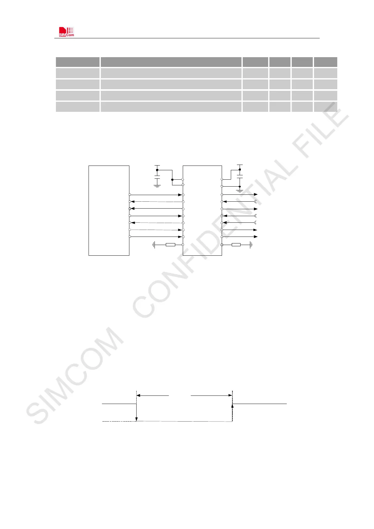
The SIM7000 UART is 1.8V voltage interface. If user’s UART application circuit is 3.3V voltage
interface, the level shifter circuits should be used for voltage matching. The following figure shows
the voltage matching reference design.
TXD
RXD
RTS
CTS
DTR
DCD
RI
A7
A1
A2
A3
A4
A5
A6
MODULE
TXB0108 RGYR
UART
A8
B7
B1
B2
B3
B4
B5
B6
B8
VCCA
OE
VDD_ EXT
100nF
3.3V
100nF
VCCB
GND
TXD_3.3V
RXD_3.3V
RTS_3.3V
CTS_3.3V
DTR_3.3V
DCD_3.3V
RI_3.3V
47K 47K
Figure 15: Reference circuit of level shift
Note: When it uses the level shifter IC, the pull up resistance
on TXD_3.3V, RTS_3.3V,
DCD_3.3V and RI_3.3V should not be less than 47K
Ω
.
3.3.2 RI and DTR Behavior
The RI pin description:
The RI pin can be used to interrupt output signal to inform the host controller such as application
CPU. Before that, users must use AT command “AT+CFGRI=1” to enable this function.
Normally RI will keep high level until certain conditions such as receiving SMS, or a URC report
coming, then it will output a low level pulse 120ms, in the end, it will become high level.
Idle
HIGH
LOW
Receiving SMS and any URC
report coming
RI
120ms
Figure 16: RI behaviour(SMS and URC report)
The DTR pin description:
After setting the AT command “AT+CSCLK=1”, and then pulling up the DTR pin, SIM7000 will