Smart Machine Smart Decision
SIM7000 _Hardware Design _V1.04 2018-1-31
enter sleep mode when module is in idle mode. In sleep mode, the UART is unavailable. When
SIM7000 enters sleep mode, pulling down DTR can wake up module.
After setting the AT command “AT+CSCLK=0”, SIM7000 will do nothing when the DTR pin is
pulling up.
Note: For more details of AT commands about UART, please refer to document [1] and [20].
3.4 USB Interface
The SIM7000 contains a USB interface compliant with the USB2.0 specification as a peripheral,
but the USB charging function is not supported.
USB_VBUS is the detecting signal for USB inserting. The input voltage range on the USB_VBUS
pin is from 3.5V to 5.25V. If there is out of this range, it may be due to USB function
unidentifiable, even damaging the module.
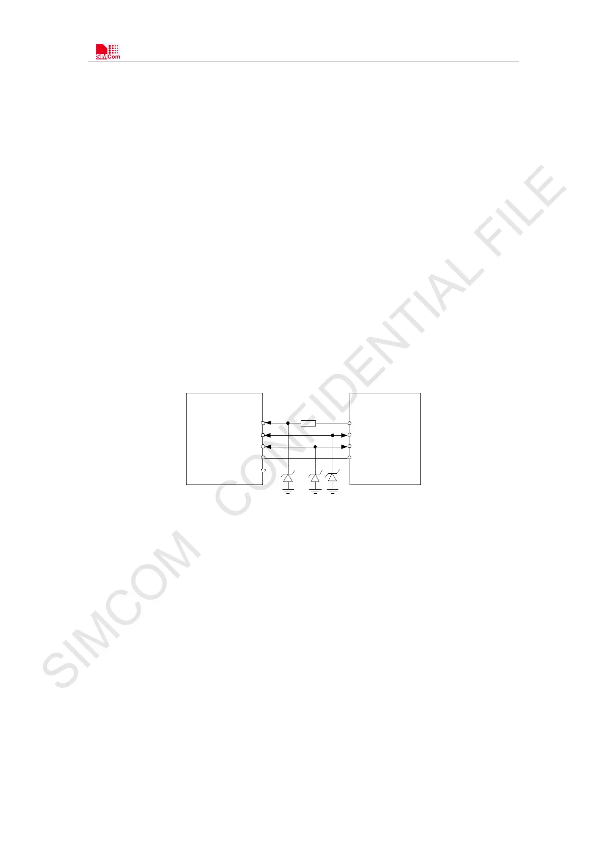
The reference circuit refers to the following figure.
USB_ VBUS
USB_DM
USB_DP
GND
USB
USB
VBUS
D-
D+
GND
D2
D1
0Ω
USB_ID
D3
MODULE HOST
Figure 17: USB reference circuit
Because of the high speed on USB bus, more attention should be paid to the influence of the
junction capacitance of the ESD component on USB data lines. Typically, the capacitance of the D1
and D2 should be less than 1pF.
D3 is suggested to select the diode with anti-ESD and voltage surge function, or customer could
add a ZENER diode for surge clamping.
Note
:
The USB_DM and USB_DP nets must be traced by 90Ohm+/-10% differential
impedance.