EasyManua.ls Logo

SimCom SIM7000 User Manual

SimCom SIM7000
74 pages
To Next Page IconTo Next Page
To Previous Page IconTo Previous Page
Page #51 background imageLoading...
Page #51 background image
Smart Machine Smart Decision
SIM7000 _Hardware Design _V1.04 2018-1-31
power-off, but the module remains registered on the network and there is no need to re-attach or
re-establish the network connections. So in PSM all the functions will be unavailable except the
RTC function, module cannot immediately respond users’ requests.
When the module wants to use the PSM, it can be enabled via “AT+CPSMS=1” command. The
command takes effect after module reboot. If the network supports PSM and accepts that the
module uses PSM, the network confirms usage of PSM by allocating an Active Time value to the
module. Module will be into PSM according to the command from network.
Either of the following methods will wake up the module from PSM:
Pulling PWRKEY pin to low level will wake up the module.
When the timer expires, the module will be automatically woken up.
5.3.5 Extended Mode DRX (e-DRX)
In idle or sleep mode, module and the network may negotiate over non-access stratum signaling the
use of extended mode DRX for reducing power consumption.
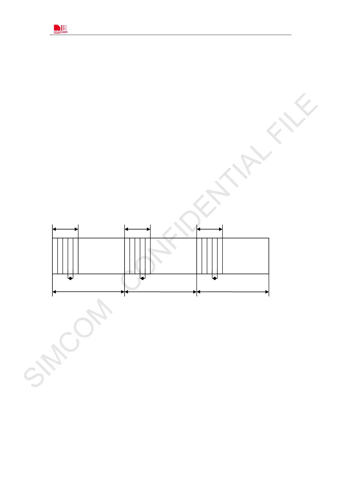
E-DRX diagrammatic sketch refer to the following figure.
Figure 31: e-DRX diagrammatic sketch
When module and the network negotiate stratum signaling in idle mode or sleep mode, extended
mode DRX can decrease the times of paging time window (PTW) and increase the cycle length.
For this reason it had reduced the times of DRX, and had reduced the frequency of DRX between
module and the network. So that can reduce power consumption for module.
If e-DRX is supported by the network, then it can be enabled byAT+CEDRXS” command.
Note: For details about “AT+CEDRXS”, please refer to Document [1].
Cycle length
Cycle length
Cycle length
ptw ptw ptw
DRX DRX DRX
···
SIMCOM CONFIDENTIAL FILE

Table of Contents

Question and Answer IconNeed help?

Do you have a question about the SimCom SIM7000 and is the answer not in the manual?

SimCom SIM7000 Specifications

General IconGeneral
BrandSimCom
ModelSIM7000
CategoryGSM/GPRS Modules
LanguageEnglish

Summary

Package Information

Pin Assignment Overview

Shows the pin layout and assignment for the SIM7000 module's 68 pads.

Pin Description

Details the function, type, and status of each pin on the SIM7000 module.

Interface Application

Power Supply

Details VBAT power input, voltage requirements, and current considerations.

Power on/Power off/Reset Function

Explains how to power on, power off, and reset the SIM7000 module.

SIM Interface

Covers the SIM card interface, voltage modes, and connection guidelines.

RF Specifications

GSM/LTE RF Specifications

Lists conducted transmission power and MPR for various GSM/LTE bands.

GSM/LTE Antenna Design Guide

Provides guidance on antenna connection, trace impedance, and matching circuits.

RF traces note

Electrical Specifications

Absolute maximum ratings

Lists the absolute maximum voltage ratings for various pins of the SIM7000.

Operating conditions

Specifies recommended operating voltage, digital I/O characteristics, and temperature.

Operating Mode

Defines various operating modes like Sleep, Idle, PSM, and e-DRX.

ESD Notes

Provides guidelines for ESD protection and measurement performance.

SMT Production Guide

Appendix

Safety Caution

Provides essential safety precautions for using the SIM7000 module.