Smart Machine Smart Decision
SIM7000 _Hardware Design _V1.04 2018-1-31
3.1.1 Power Supply Design Guide
Make sure that the voltage on the VBAT pins will never drop below 3.0V, even during a transmit
burst when current consumption may rise up to 2A. If the voltage drops below 3.0V, module will be
shutdown.
Note: If the power supply for VBAT pins can support up to 2A, using a total of more than 300uF
capacitors is recommended, or else users must using a total of 1000uF capacitors typically, in
order to avoid the voltage drop is more than 300mV.
Some multi-layer ceramic chip (MLCC) capacitors (0.1uF, 1uF) with low ESR in high frequency
band can be used for EMC.
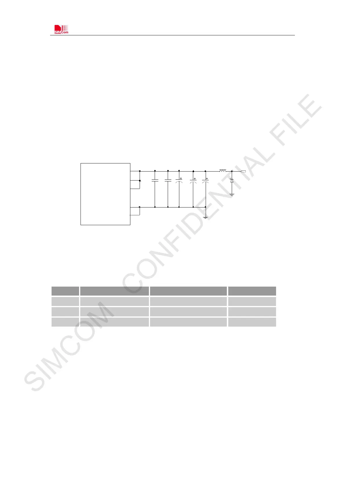
These capacitors should be put as close as possible to V BAT pads. Also, users should keep VBAT
trace on circuit board wider than 2 mm to minimize PCB trace impedance. The following figure
shows the recommended circuit.
VBAT
VBAT
VBAT
GND
MODULE
FB101
TVS
VBAT
Cb
100uF
1uF
Ce
Cc
100uF
Ca
Cd
100uF
100nF
GND
Figure 6: Power supply application circuit
In addition, for ESD protection, it is suggested to add a TVS diode near t h e V B AT PINs.
Table 7: Recommended TVS diode list
No. Manufacturer Part Number Package
3 WILLsemi ESD5651N-2/TR DFN1006
3.1.2 Recommended Power Supply Circuit
It is recommended that a switching mode power supply or a linear regulator power supply is used.
It is important to make sure that all the components used in the power supply circuit can resist a
peak current up to 2A when used GPRS/EDGE.
The following figure shows the linear regulator reference circuit with 5V input and 3.8V output.
But this linear regulator has a minimum load current, and it is even bigger than 7mA. So if users
care the system power consumption very much, it is not recommended to use.