Smart Machine Smart Decision
SIM7000 _Hardware Design _V1.04 2018-1-31
3 Interface Application
3.1 Power Supply
Pin 55, pin 56 and pin 57 are VBAT power input.
On VBAT pads, when module works on CAT-M1 or NB-IoT mode, the ripple current is up to 0.6A
typically. For steady voltage, the power supply capability must be up to 0.6A.
On VBAT pads, when module works on EDGE or GPRS mode, he ripple current is up to 2A
typically. For steady voltage, the power supply capability must be up to 2A.
in order to avoid the voltage dropped down more than 300mV, the load capacitor on VBAT pads
must be up to 300uF.
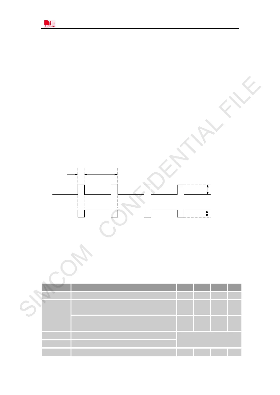
The following figure shows the VBAT voltage ripple wave at the maximum power transmit phase
in EDGE/GPRS emission mode.
577us 4.615ms
Burst:2A
I
VBAT
VBAT
Max:300mV
Figure 5: VBAT voltage drop during burst emission (EDGE/GPRS)
Note: The test condition: The voltage of power supply for VBAT is 3.8V, Ca=100 µF tantalum
capacitor (ESR=0.7Ω) and Ce =100nF (Please refer to Figure 6—Application circuit).
Table 6: VBAT pins electronic characteristic
Symbol Description Min. Typ. Max. Unit
V B AT
Module power voltage
3.0
3.8
4.3
V
I
VBAT(peak)
Module power peak current in GSM and EDGE emission
mode.
- 2 - A
Module power peak current in C AT-M1 and NB-IoT
mode.
- 0.6 - A
I
VBAT(average)
Module power average current in normal mode
Please refer to the chapter 5.4
I
VBAT(sleep)
Power supply current in sleep mode
I
VBAT(power-off)
Module power current in power off mode.
-
-
7
uA