Smart Machine Smart Decision
SIM7000 _Hardware Design _V1.04 2018-1-31
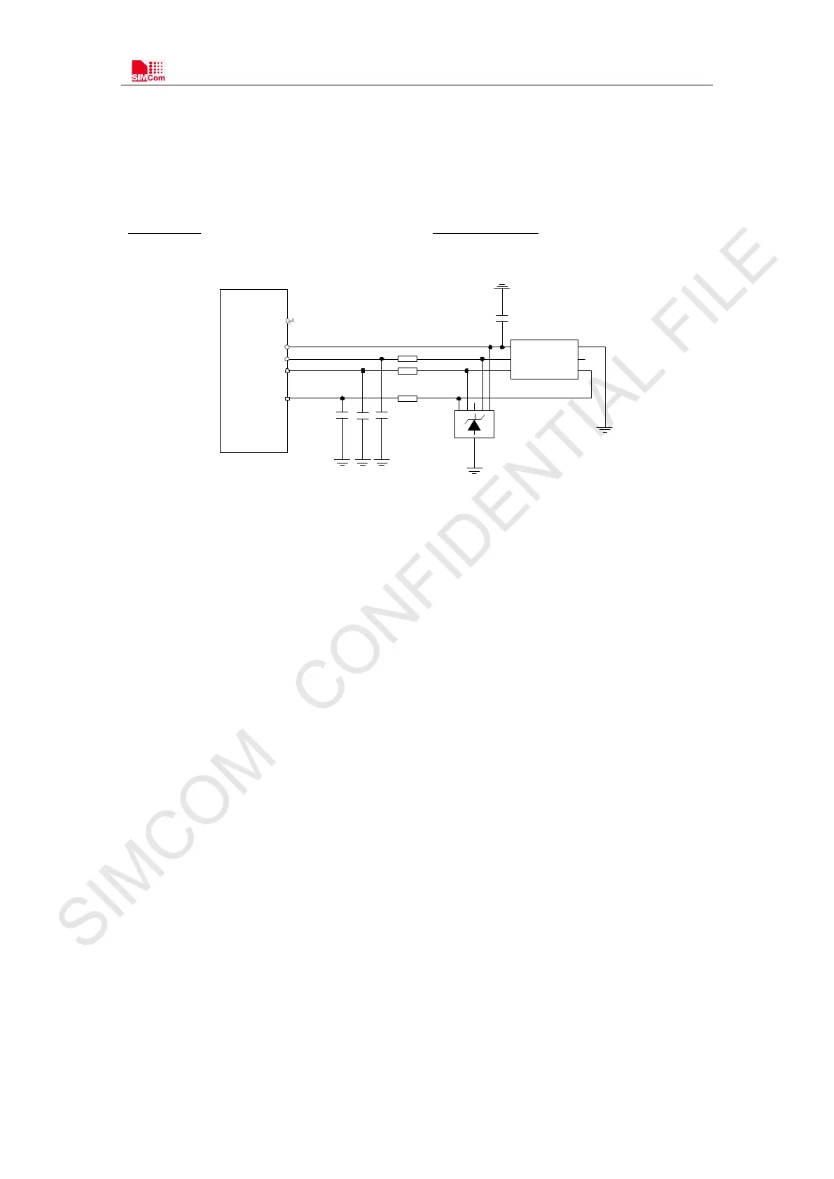
3.5.1 SIM Application Guide
It is recommended to use an ESD protection component such as ESDA6V1W5 produced by ST
(
www.st.com ) or SMF15C produced by ON SEMI (www.onsemi.com ). Note that the SIM
peripheral circuit should be close to the SIM card socket. The following figure shows the 6-pin
SIM card holder reference circuit.
MODULE
TVS
SIM_ VDD
SIM_ CLK
SIM_ DATA
SIM_ RST
VCC GND
RST VPP
CLK I / O
22
Ω
100nF
C707 10M 006 512
SIM Socket
22
Ω
22
Ω
NC
NC
NC
SIM_ DET
Figure 18: SIM interface reference circuit
SIM_DATA has been pulled up with a 10KΩ resistor to SIM_VDD in module, so it no need
pulled up resistor anymore.
SIM_VDD is need a 100nF capacitor close to SIM socket.
SIM_CLK is very important signal, the rise time and fall time of SIM_CLK should be less
than 40ns. So the junction capacity of the TVS need to less 50pF.
SIM_DET is the detecting signal for SIM card to insert and pull out. There is no pull up
resistor in module, so a 10KΩ resistor is necessary to pulling up to the power VDD_EXT. This
function is disabled default by software. Users can enable it by AT comment “AT +CSD T ”. And the
Interruption direction can be set by AT comment “AT +C SP O L”.
Note
:
For more details of AT commands about “AT+CSDT” and “AT+CSPOL”, please refer to
document [1]