Smart Machine Smart Decision
SIM7000 _Hardware Design _V1.04 2018-1-31
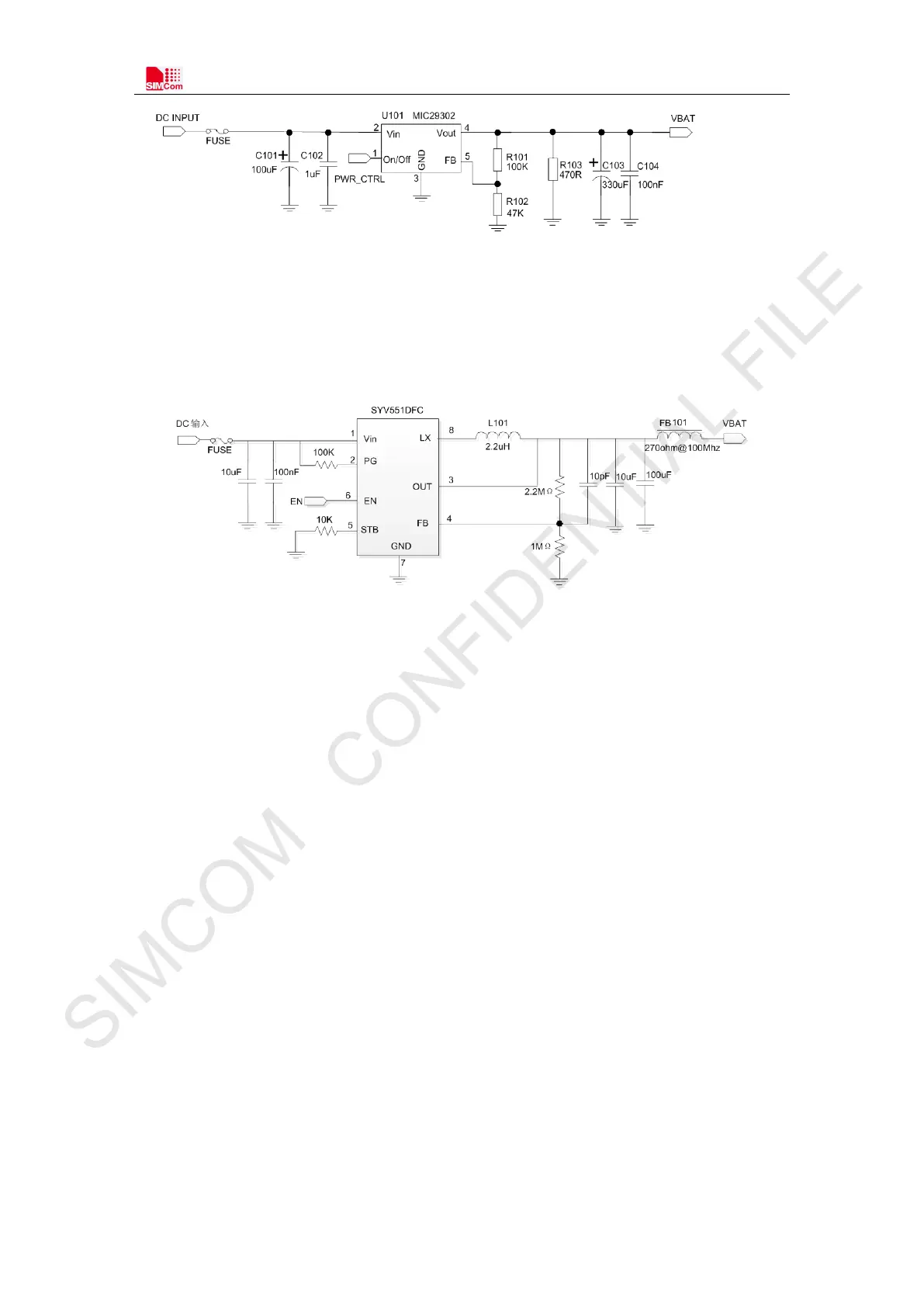
Figure 7: Linear regulator reference circuit
If users used LTE mode only and never used EDGE/GPRS mode, switching mode power supply is
recommended to use. And the maximum output current must be meeting the requirement. The
following figure shows the switching mode power supply reference circuit.
Figure 8: power supply reference circuit (NB only)
3.1.3 Voltage Monitor
To monitor the V B AT voltage, the AT command “AT+CBC” can be used.
AT command “ AT + CB AT C H K=1” can be used to enable the overvoltage warning function and the
under-voltage warning function. The default value of the overvoltage warning function in the
software is 4.3V, and the default value of the under-voltage warning function is 3.1V. If the power
supply for VBAT pins is up 4.3V or under 3.1V, module will be warning.
The AT command “AT+CBATCHK=1” also can be used to enable the overvoltage power-off
function and the under-voltage power-off function. The default value of the overvoltage power-off
function is 4.4V, and the default value of the under-voltage power-off function is 2.9V. If the VB AT
voltage is up 4.4V or under 2.9V, module will be power off.
Note: Under-voltage warning function and under-voltage power-off function are disabled by
default. For more information about these AT commands, please refer to Document [1].