Smart Machine Smart Decision
SIM7000 _Hardware Design _V1.04 2018-1-31
B. Design check list
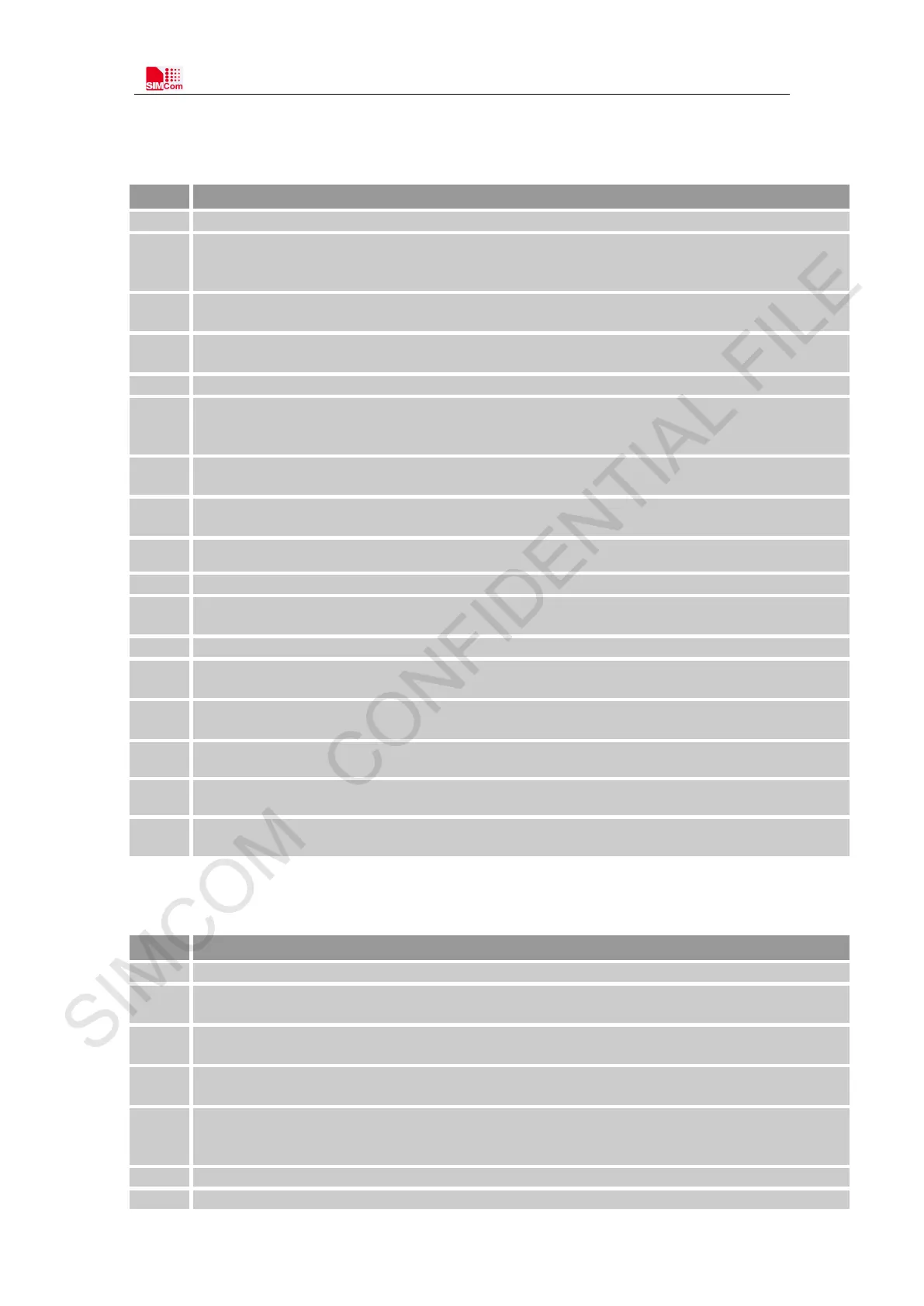
Table 41: Schematic Check List
Insure the supply voltage for VBAT is within the range of 3V~4.3V.
2
Insure the maximum supply current for VBAT is above its consumption when it is maximum
power emission.
The maximum current is 2A during GPRS/EDGE emission maximum power, and
it 0.6A during LTE emission maximum power.
3
Insure the capacitor for VBAT is meet its request, in order to avoid the voltage drop exceed
300mV. And the voltage never dropped below 3V.
4
Insure the input signal for PWRKEY pin meet its electrical level match. It recommended use BJT
to shift its level.
Insure the input signal for NRESET pin meet its electrical level match.
6
Insure the net connections of UART be correctness according to signal direction. Insure the signal
for UART pins meet its electrical level match. It recommended use BJT or level shift IC to shift
7
Insure USB port had used TVS to protect signal. And the junction capacity of TVS for DP/DM
must be less than 1pf.
8
Insure SIM card signal had used TVS to protect. And the junction capacity of TVS must be less
than 50pf.
9 Insure SIM_DET had used resistor 10Kohm pull up to VDD_EXT if used this signal.
Insure I2C signal had used resistors 2.2Kohm pull up to VDD_EXT if used.
11
The electrical level of all GPIOs is 1.8V. Insure the signal for GPIO pins meet its electrical level
match.
The input range of ADC is 0V~V B AT. Insure the input signal never exceed its range.
13
User must pull up DTR when module enters into sleep mode. Insure DTR can be controlled by
host.
14
Suggesting to reserve test ports for VDD_EXT and BOOT_CFG. BOOT_CFG should keep open
before boot up.
15 The power supply of the active antenna should be controlled and closed.
16 LTE main ANT should have a PI type matching to debug antenna
17
LTE main ANT should Keep TVS to prevent ESD destroyed. And the TVS should be Low
junction capacitance.
Table 42: PCB Layout Check List
NO. Items
Insure the capacitor placement for VBAT be near module pin.
2
Insure VBAT trace width be greater than 2mm. If NB only, insure VBAT trace width be greater
than 0.6mm. And the VIA number must be enough for getting through the current.
3
Insure the return path GND of the power supply is good. Insure the connectivity between module
GND and mother board GND is good.
4
Insure PCM trance is protected by GND, and keep it far from interference source, such as power
supply trace, USB trace, RF trace and so on.
5
Insure USB trance is protected by GND, and keep it far from interference source, such as power
supply trace, RF trace and so on. Insure DM/DP trace is differential routing, and differential
Insure ADC trance is protected by GND.
Insure SIM card signal trance is protected by GND. Especially SIM_CLK must be protected