SIM900 Hardware Design
z Via PWRKEY pin: starts normal operating mode (please refer to chapter 3.4.1.1);
z Via PWRKEY pin and PWRKEY_OUT pin:starts normal operating mode
Note: The AT command must be set after the SIM900 is power on and Unsolicited Result Code “RDY” is
received from the serial port. However if the SIM900 is set autobauding, the serial port will receive nothing.
The AT commands can be set after the SIM900 is power on. You can use AT+IPR=x to set a fixed baud rate
and save the configuration to non-volatile flash memory. After the configuration is saved as fixed baud rate,
the Code “RDY” should be received from the serial port all the time that the SIM900 is power on. Please refer
to the chapter AT+IPR in document [1].
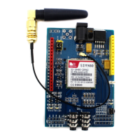
3.4.1.1 Turn on SIM900 Using the PWRKEY Pin (Power on)
You can turn on the SIM900 by driving the PWRKEY to a low level voltage with a limiting current resistor (1K
is recommended) in series for a short time and then release. This pin has pulled up to VDD_EXT in the module.
The simple circuit illustrates as the following figures.
4.7K
47K
Turn on impulse
PWRKEY
1K
Figure 6: Turn on SIM900 using driving circuit
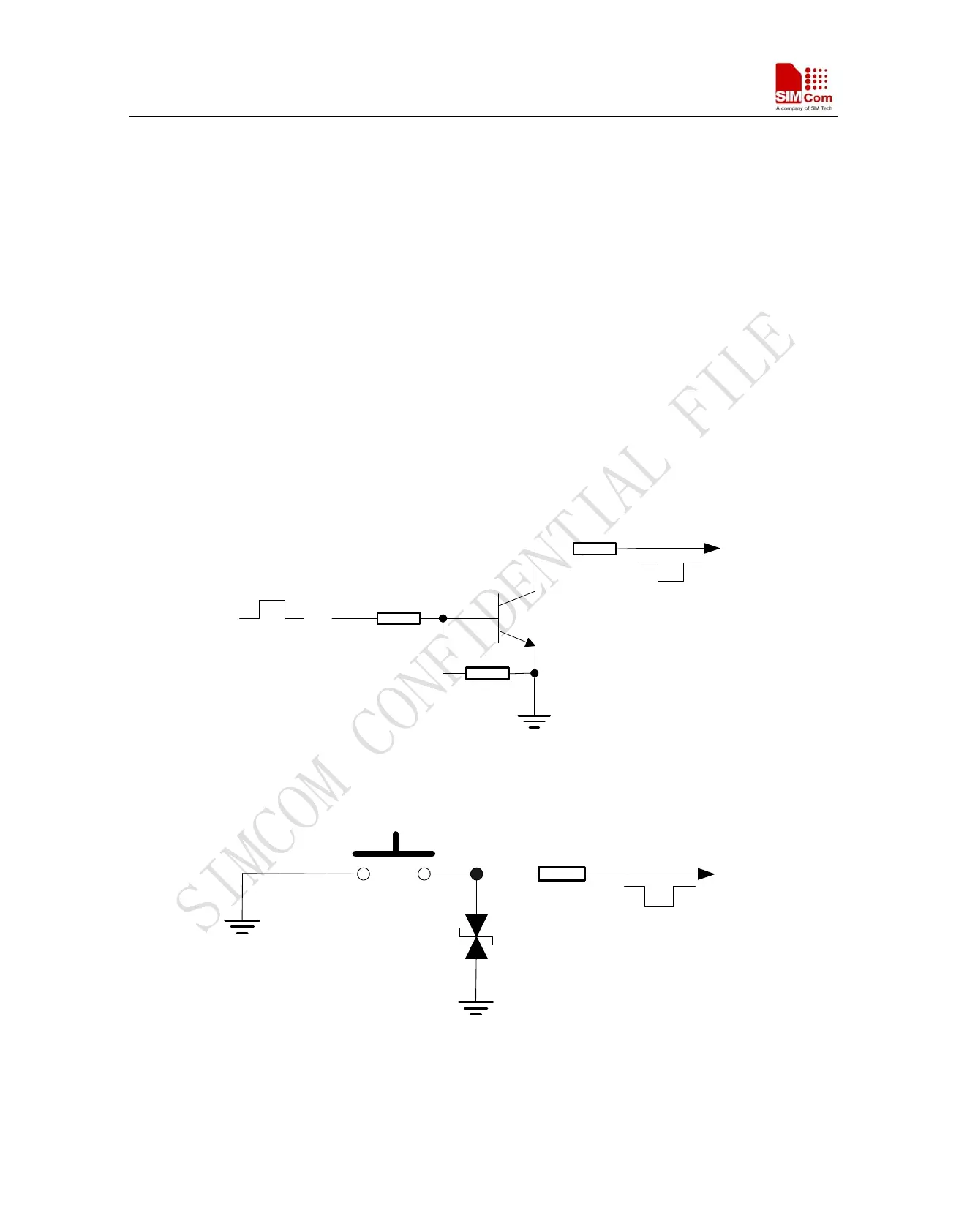
S1
PWRKEY
TVS1
1K
Figure 7: Turn on SIM900 using button
SIM900_HD_V1.05 06.23.2010
24