SIM900 Hardware Design
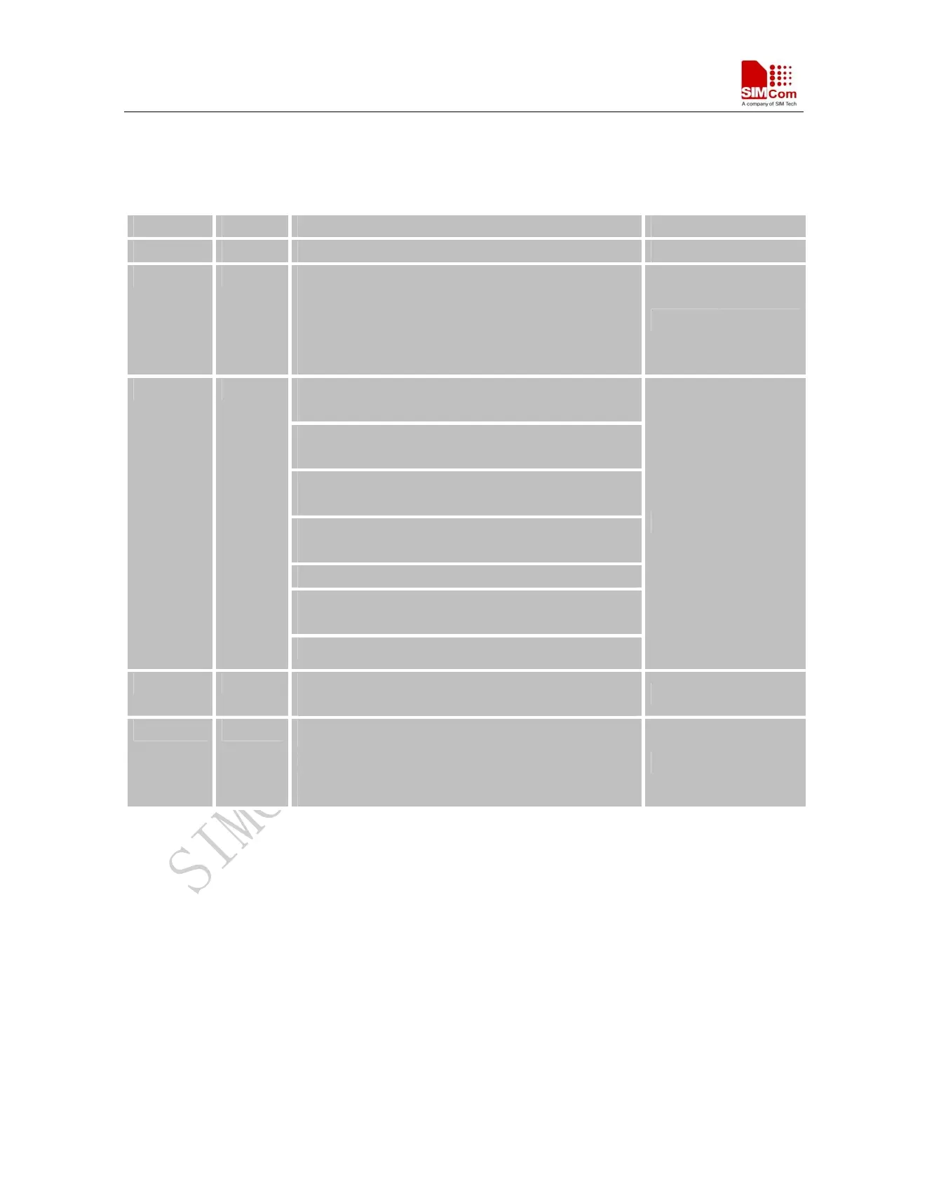
Version history
Date Version Description of change Author
2009-12-26 1.01 Origin LiGang
2010-02-04 1.02 Modify the voltage range of ADC input.
Modify the figure of bottom mechanical dimensions of
module.
Modify the figure of recommended PCB decal and the
note.
LiGang
§2, § 2.1 Changed the lowest current consumption in
sleep mode from 1.5mA to 1.0mA.
§3.1 Add the description of the RXD pin, this pin should
be pulled up to VDD_EXT.
§3.4.2.1 Change the pull down time of the figure 12.
Change the impulse time of the figure 13.
§3.8.1 Update the description of autobauding. The
default setting is autobauding mode.
§3.9.4 Add audio parameters in table 10 and table 11.
§3.10.1 Change the value of the capacitance from 220nF
to 100nF in figure 27 and figure 28.
2010-04-07 1.03
§3.13 Delete the pull up resistor of figure 32.
LiGang
2010-05-07 1.04 §2.1, § 3.4.2.3 Modify the power supply range from
3.4V~4.5V to 3.2V~4.8V.
LiGang
2010-06-23 1.05 §3.7, Modify the VRTC pin connection when backup is
not needed.
§3.4, Revise Figure 8 & Figure 11
§5.3 Revise the Supply Voltage Range
ZhouQiang
SIM900_HD_V1.05 7 05.07.2010