SIM900 Hardware Design
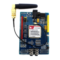
300R
4.7K
47K
SIM900
MODULE
NETLIGHT
VBAT
Figure 35: Reference circuit of NETLIGHT
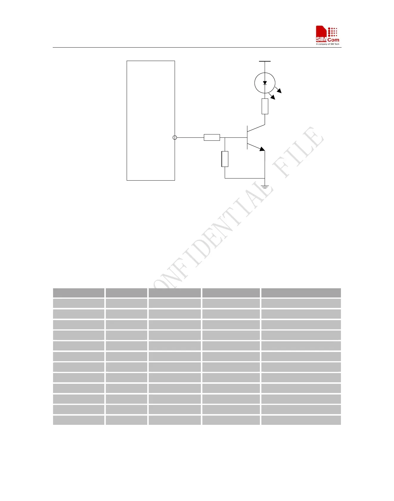
3.16 General Purpose Input Output (GPIO)
SIM900 provides a limited number of General Purpose Input/Output signal pin. The output and input voltage level
of the GPIO can be set by AT command. For more details, please refer to document [1]
Table
20: Pin define of the GPIO interface
Pin Name Pin Number Default Function Second Function* Default State
GPIO1/ KBR4 40 GPIO1 KBR4 Output Pull down
GPIO2/ KBR3 41 GPIO2 KBR3 Output Pull down
GPIO3/ KBR2 42 GPIO3 KBR2 Output Pull down
GPIO4/ KBR1 43 GPIO4 KBR1 Output Pull down
GPIO5/ KBR0 44 GPIO5 KBR0 Output Pull down
GPIO6/ KBC4 47 GPIO6 KBC4 Output Pull down
GPIO7/ KBC3 48 GPIO7 KBC3 Output Pull down
GPIO8/ KBC2 49 GPIO8 KBC2 Output Pull down
GPIO9/ KBC1 50 GPIO9 KBC1 Output Pull down
GPIO10/ KBC0 51 GPIO10 KBC0 Output Pull down
GPIO11 67 GPIO11 Output Pull down
GPIO12 68 GPIO12 Output Pull down
*Note: This function is not supported in the default firmware. There must be customized firmware if you want.
Please contact SIMCom for more details.
SIM900_HD_V1.05 06.23.2010
46