SIM900 Hardware Design
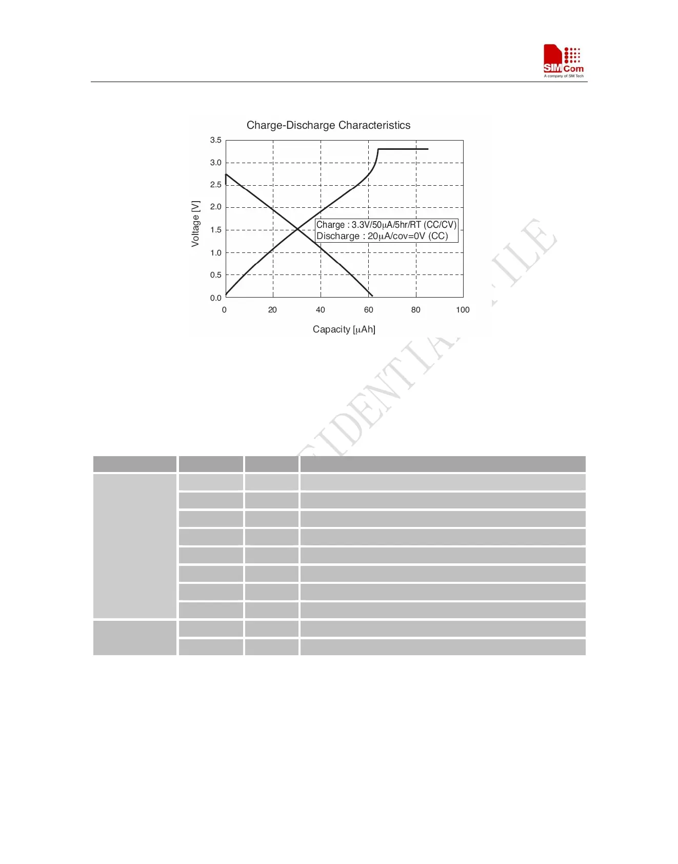
Typical charge curves for each cell type are shown in following figures. Note that the rechargeable Lithium type
coin cells generally come pre-charged from the vendor.
Figure 19: Seiko XH414H-IV01E Charge Characteristic
3.8 Serial Interfaces
Table 7: Pin definition of the serial interfaces
Name Pin Function
DTR 3 Data terminal ready
RI 4 Ring indicator
DCD 5 Data carrier detection
DSR 6 Date set ready
CTS 7 Clear to send
RTS 8 Request to send
TXD 9 Transmit data
Serial port
RXD 10 Receive data
DBG_RXD 28 Receive data
Debug port
DBG_TXD 27 Transmit data
SIM900 provides two unbalanced asynchronous serial ports. One is the serial port and the other is the debug port.
The GSM module is designed as a DCE (Data Communication Equipment), following the traditional DCE-DTE
(Data Terminal Equipment) connection. The module and the client (DTE) are connected through the following
signal (as following figure shows). Autobauding supports baud rate from 1200bps to 57600bps.
Serial port
z TXD: Send data to the RXD signal line of the DTE
z RXD: Receive data from the TXD signal line of the DTE
Debug port
SIM900_HD_V1.05 06.23.2010
32