SIM900 Hardware Design
Figure 21: Connection of software upgrade and software debug
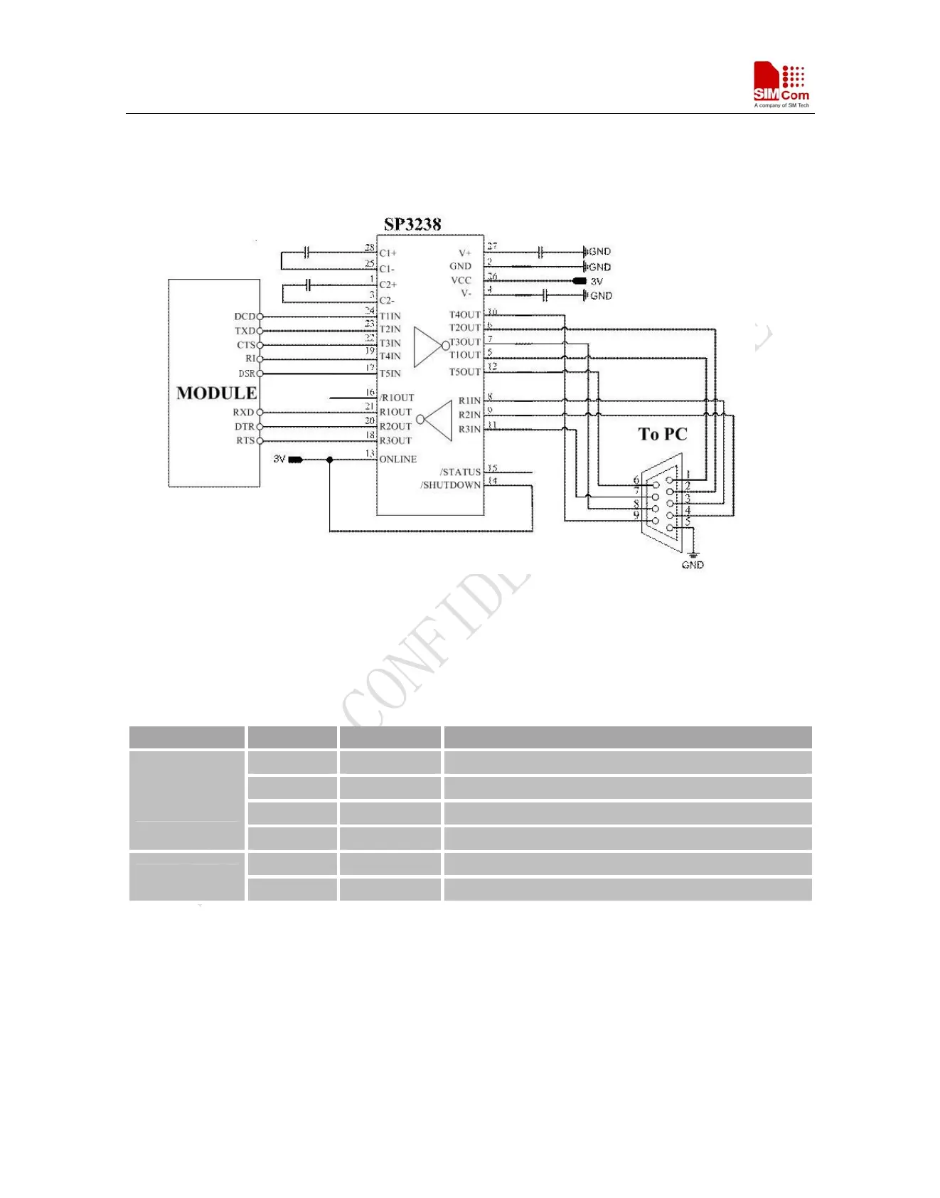
The serial port and the debug port don’t support the RS_232 level and it only supports the CMOS level. Please
refer to the table 10 for details about the voltage level. You should add the level converter IC between the DCE
and DTE, if you connect it to the computer. Please refer to the following figure.
Figure 22: RS232 level converter circuit
3.9 Audio Interfaces
Table 9: Pin define of the Audio interface
Pin Name Pin Number Function
MIC_P 19 Microphone1 input +
MIC_N 20 Microphone1 input -
SPK_P 21 Audio1 output+
AIN/AOUT
SPK_N 22 Audio1 output-
LINEIN_R 23 Right Channel input
LINE IN
LINEIN_L 24 Lift Channel input
The module provides one analog input channel, AIN, which may be used for microphone. The electret
microphone is recommended when the interface is used for microphone. The outputs connect to the receiver. The
receiver outputs only can directly drive 32Ω.
External line inputs are available to directly mix or multiplex externally generated analog signals such as
polyphonic tones from an external melody IC or music generated by an FM tuner IC or module.
You can use AT+CMIC to adjust the input gain level of microphone, use AT+SIDET to set the side-tone level. In
addition, you can also use AT+CLVL to adjust the output gain level. For more details, please refer to document
[1].
SIM900_HD_V1.05 06.23.2010
35