SIM900 Hardware Design
Table 16: Pin define of the keypad interface
Pin Name Pin Number Default
Function
Second Function* Default State
GPIO1/ KBR4 40 GPIO1 Output Pull down
GPIO2/ KBR3 41 GPIO2 Output Pull down
GPIO3/ KBR2 42 GPIO3 Output Pull down
GPIO4/ KBR1 43 GPIO4 Output Pull down
GPIO5/ KBR0 44 GPIO5
Keypad matrix column
Output Pull down
GPIO6/ KBC4 47 GPIO6 Output Pull down
GPIO7/ KBC3 48 GPIO7 Output Pull down
GPIO8/ KBC2 49 GPIO8 Output Pull down
GPIO9/ KBC1 50 GPIO9 Output Pull down
GPIO10/ KBC0 51 GPIO10
Keypad matrix row
Output Pull down
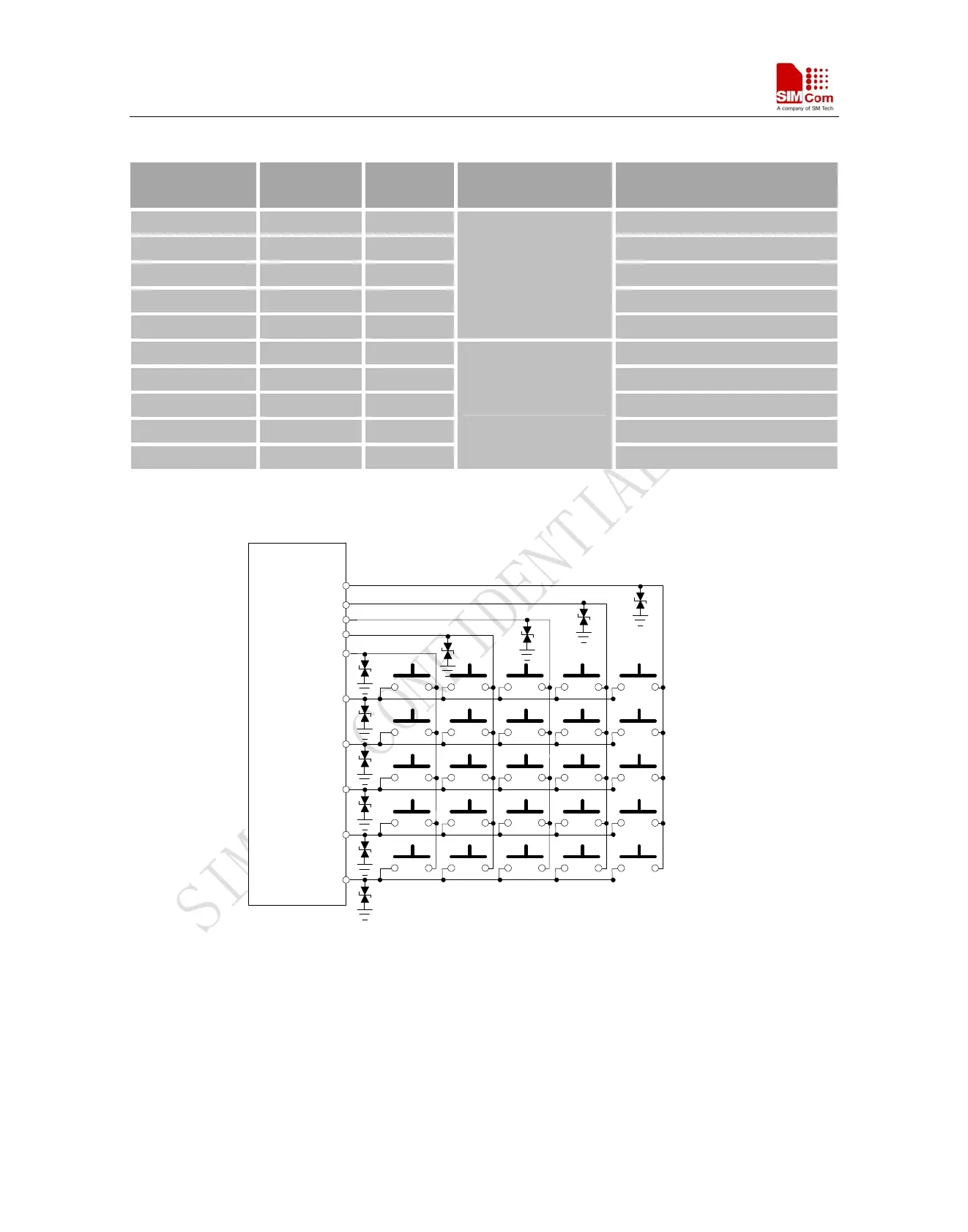
The keypad interface allows a direct external matrix connection. A typical recommended circuit about the keypad
is as shown in the following figure.
KBR4
KBR3
KBR2
KBR1
KBR0
KBC0
KBC1
KBC2
KBC3
KBC4
GND
MODULE
Figure 31: Reference circuit of the keypad interface
*Note: This function is not supported in the default firmware. There must be customized firmware if you want.
Please contact SIMCom for more details.
SIM900_HD_V1.05 06.23.2010
43