SIM900 Hardware Design
3.13 ADC
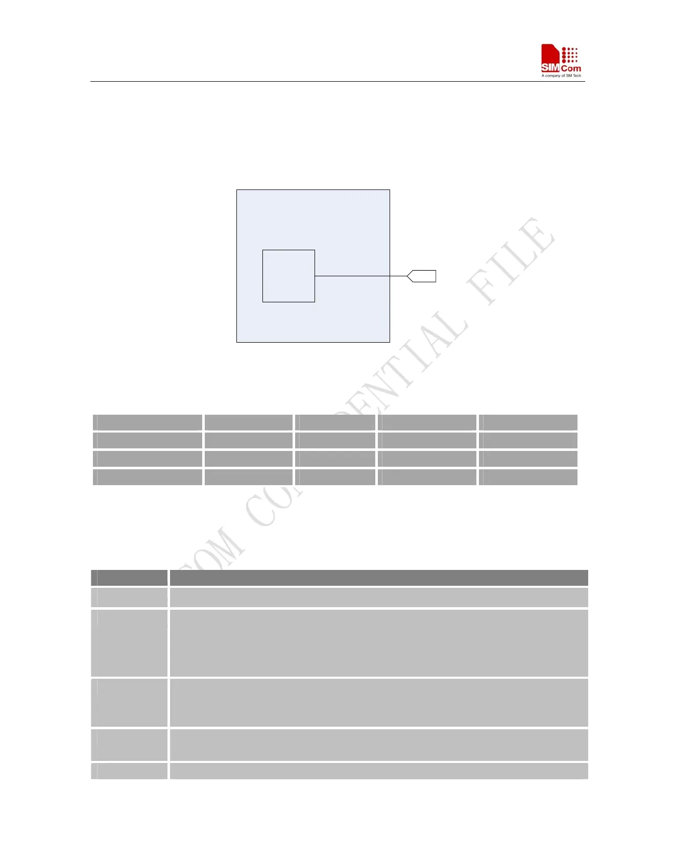
SIM900 provides one auxiliary ADC (General purpose analog to digital converter.) as voltage input pin, which
can be used to detect the values of some external items such as voltage, temperature etc. We can use AT
command “AT+CADC” to read the voltage value on ADC. For detail of this AT command, please refer to
document [1].
ADC
AUX
ADC
MODULE
Figure 32: Architecture of ADC
Table
17: ADC specification
MIN Type MAX Units
Voltage range 0 - 2.8 V
ADC Resolution - 10 - bits
Sampling rate - - 200K Hz
3.14 Behaviors of the RI
Table 18: Behaviours of the RI
State RI respond
Standby HIGH
Voice calling Change LOW, then:
(1)Change to HIGH when establish calling.
(2)Use AT command ATH, the RI pin changes to HIGH.
(3)Sender hangs up, change to HIGH.
Data calling Change LOW, then:
(1)Change to HIGH when establish calling.
(2)Use AT command ATH, the RI changes to HIGH.
SMS When receive SMS, The RI will change to LOW and hold low level about 120 ms, then
change to HIGH.
URC Some URCs triggers 120ms low level on RI. For more details, please refer to document [10]
SIM900_HD_V1.05 06.23.2010
44