SIM900 Hardware Design
Both 1.8V and 3.0V SIM Cards are supported.
The SIM interface is powered from an internal regulator in the module having normal voltage 3V. All pins reset
as outputs driving low. Logic levels are as described in table
Table
12: Pin define of the SIM interface
Pin Name Pin Number Function
SIM_VDD 30 SIM Card Power output automatic output on SIM mode,one is
3.0V±10%, another is 1.8V±10%. Current is about 10mA.
SIM_DATA 31 SIM Card data I/O
SIM_CLK 32 SIM Card Clock
SIM_RST 33 SIM Card Reset
SIM_PRESENCE 34 SIM Card detection
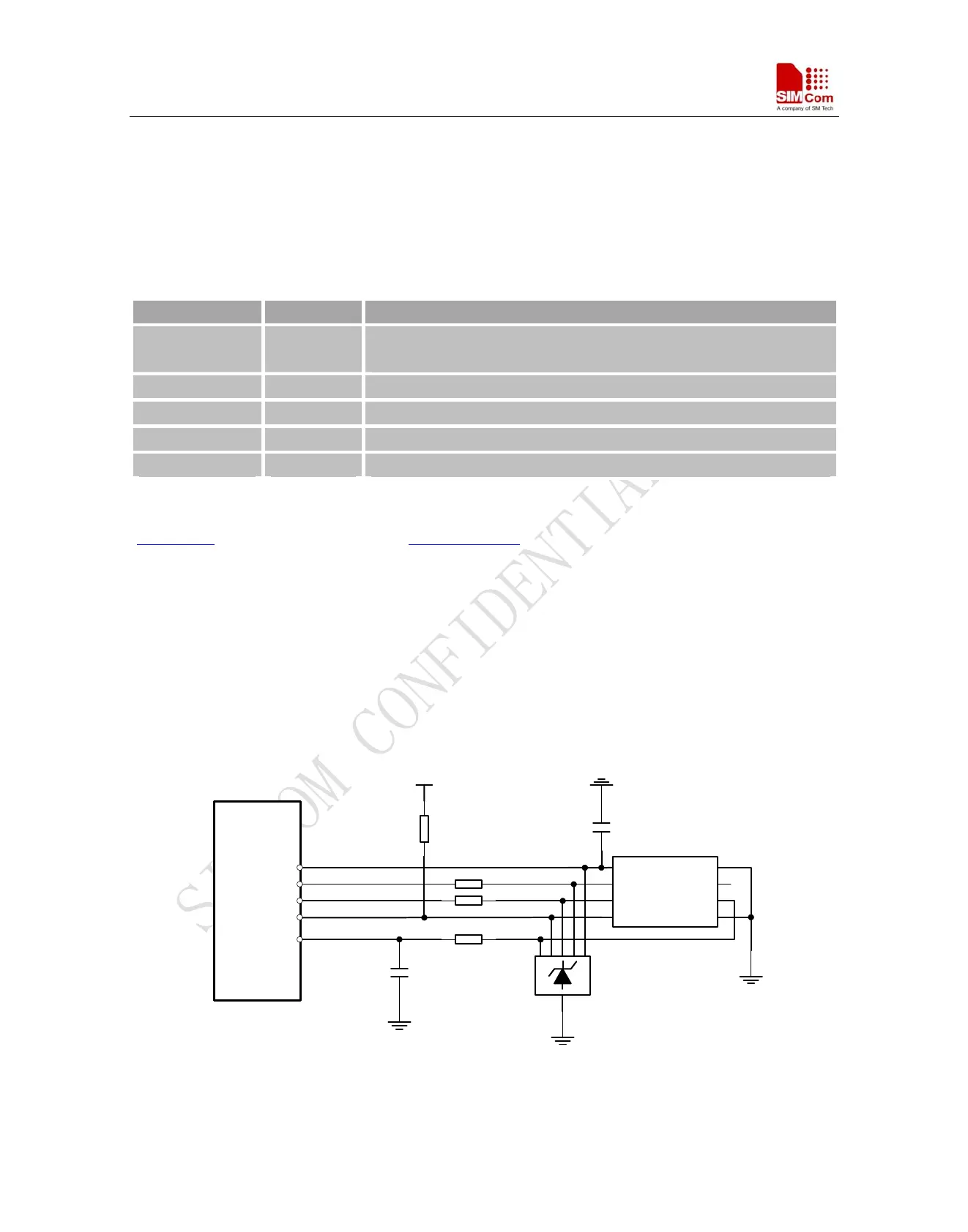
Following is the reference circuit about SIM interface. We recommend an Electro-Static discharge device ST
(www.st.com
) ESDA6V1W5 or ON SEMI (www.onsemi.com ) SMF05C for “ESD ANTI”. The 22Ω resistors
showed in the following figure should be added in series on the IO line between the module and the SIM card for
protecting the SIM I/O port. The pull up resistor (about 15KΩ) on the SIM_DATA line already added in the
module. Note that the SIM peripheral circuit should be close to the SIM card socket.
The SIM_PRESENCE pin is used for detecting the SIM card insert or removal. You can use the AT command
“AT+CSDT” to set the SIMCARD configuration. For detail of this AT command, please refer to document [1]:
You can select the 8 pins SIM card holder. The reference circuit about 8 pins SIM card holder illustrates as
following figure.
MODULE
SMF05C
SIM_VDD
SIM_CLK
SIM_DATA
SIM_RST
SIM_PRESENCE
VCC GND
RST VPP
CLK I/O
PRESENCE GND
10K
22R
22R
22R
100nF
VDD_EXT
MOLEX-91228
SIM
CARD
22pF
Figure 27: Reference circuit of the 8 pins SIM card
SIM900_HD_V1.05 06.23.2010
39