SIM900 Hardware Design
3.17 External Reset
The external NRESET pin provides a means for external circuitry to force the device into a reset state. This
signal has to be considered as an emergency reset only. Asserting an active-low signal on the NRESET pin
generates a reset; already pull up in module. A decoupling of the NRESET pin may be necessary to avoid
erroneous noise-induced resets.
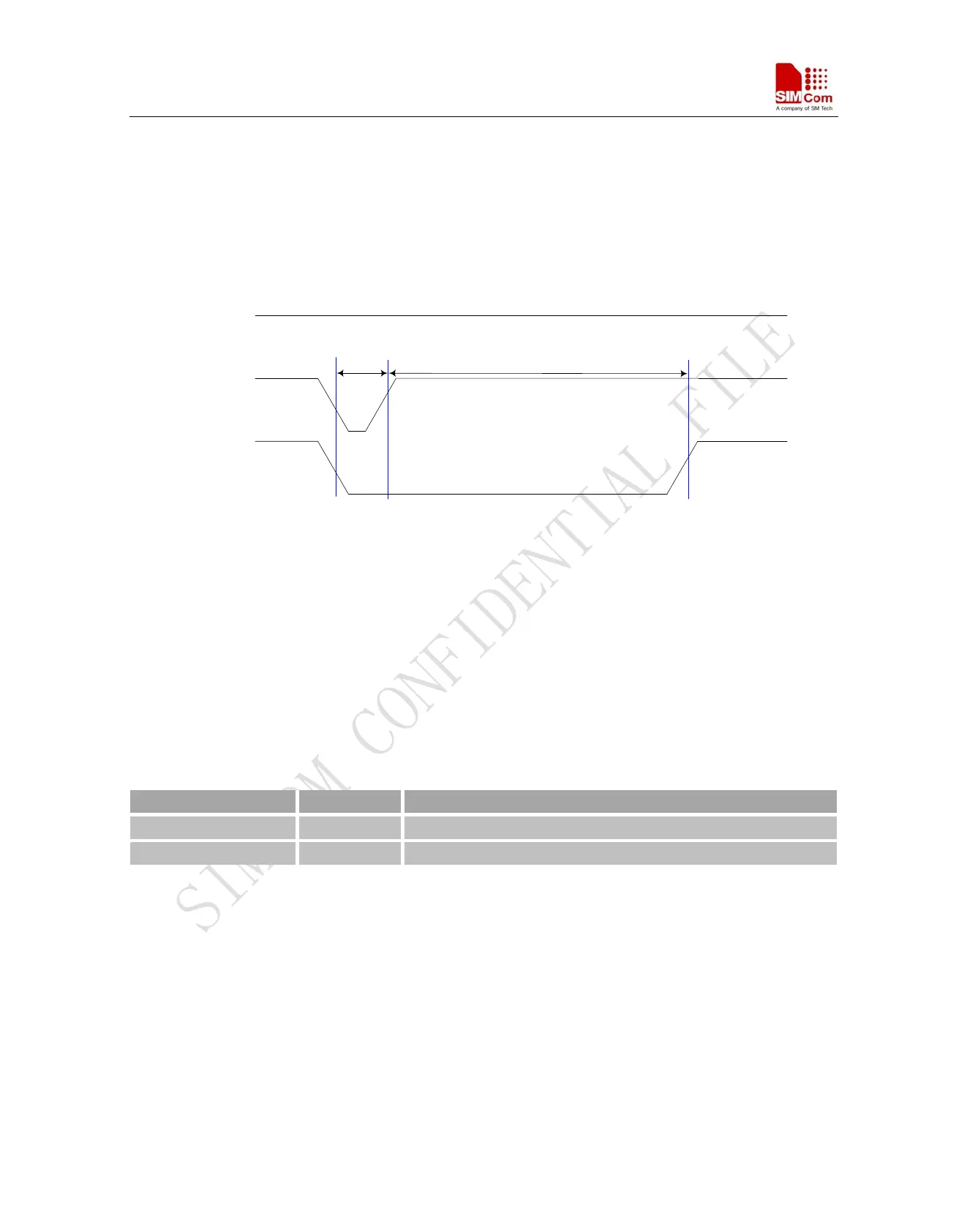
STATUS
(OUTPUT)
V
IL
<0.15*VDD_EXT
V
IH
> 0.85*VDD_EXT
VBAT
NRESET
V
OH
> 0.85*VDD_EXT
MIN:20us
TYP:50us
MIN:1.2s
V
OL
< 0.1V
Figure 36: Reset timing
3.18 PWM
SIM900 contains two DC Pulse-Width Modulators (PWMs) which can be used in conjunction with an external
transistor for driving a vibrator, or a backlight LED for illuminating an LCD display or keyboard.
Each PWM features 7-bit resolution and a maximum conversion rate is 3.25 MHz. Each PWM uses two 7-bit
unsigned binary numbers: one for the output period and one for the pulse width or the duty cycle.
Table 21: Pin define of the PWM
Pin Name Pin Number
PWM1 35 Pulse-Width Modulator Signal
PWM2 36 Pulse-Width Modulator Signal
Note: This function is not supported in the default firmware. There must be customized firmware if you want.
Please contact SIMCom for more details.
3.19 I2C Bus
The SIM900 initiates a data transfer on the bus and generates the clock signal to execute the transfer. The
features include the following:
z Maximum output rate equal to 400 kbit/s
z Open-drain outputs
z Automatic Start and Stop generation
SIM900_HD_V1.05 06.23.2010
47