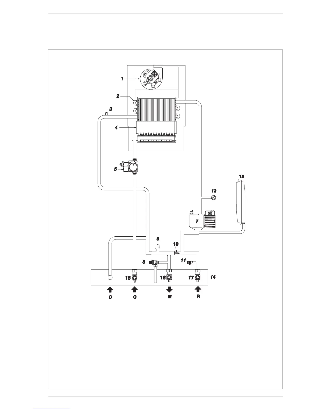
6.1.4 FUNCTIONAL DIAGRAM
Fig.6
KEY
1 Fan
2 Primaryexchanger
3 C.H.sensor(SM1/SM2)
4 Combustionchamber
5 Gasvalve
7 Pump
8 3BARsafetyvalve
9 Waterpressureswitch
10 By-pass
11 Drainvent
12 Expansionvessel
13 Hydrometer
14 Connectionplate
15 Gasisolationvalve(optional)
16 C.H.flowisolationvalve(optional)
17 C.H.returnisolationvalve(optional)
CONNECTIONS
G Gasconnection
M C.H.flow
S Safetyvalvedischarge
R C.H.return
C Fillingsystem
“30i - 30e SYSTEM” models