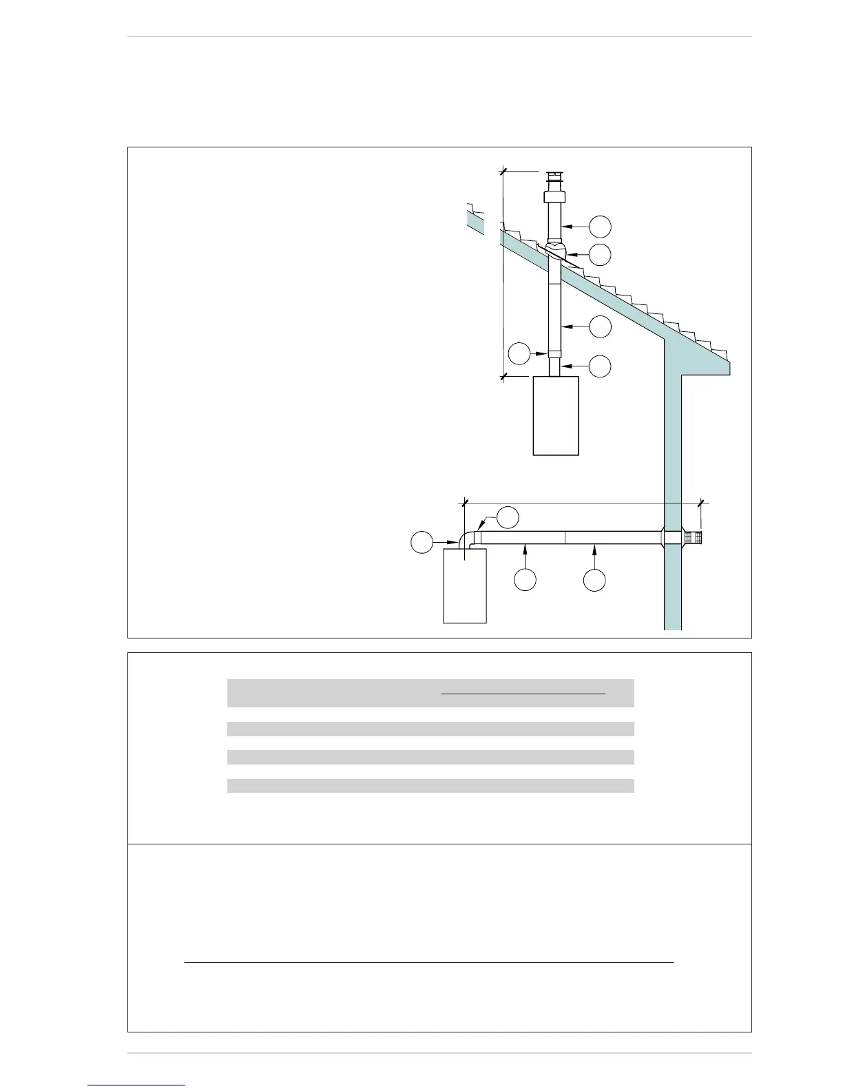
Fig.10
KEY
1 Coaxialductkitcode8084830
2 ExtensionL.1000code8096130
3 VerticalextensionL.200withcouplingcode8086908
4a Additional90°curvecode8095820
4b Additional45°curvecode8095920
5 Adapterfor80/125code8093120
6 Flashingbyothers
7 TerminalforroofexitL.1284code8091200
8 VerticalcondensationcollectorL.200code8092803
(Usedasalternativetoitem3)
IMPORTANT:
– Each additional 90° curve installed reduces the avai-
lable length by 1.0 metres.
– Each additional 45° curve installed reduces the avai-
lable length by 0.80 metres.
– The insertion of the condensation collector (8) is
obligatory in C32 discharge type.
Calculationexampleoftheheadlossofa “DGT 30i”vers.boiler(installationallowedasthesumoftheheadlosses
oftheaccessoriesusedislessthan9.5mmH
2
O–93.2Pa):
IntakeOutlet
7meterhorizontalpipeø80x0.25(2.45Pa) 1.75(17.20) –
7meterhorizontalpipeø80x0.35(3.43Pa) – 2.45(24.00)
No.290°elbowsø80x0.45(4.41Pa) 0.90(8.83) –
No.290°elbowsø80x0.50(4.90Pa) – 1.00(9.81)
No.1wallterminalø80 0.20(1.96) 0.80(7.85)
Totalheadloss 2.85(27.99) + 4.25(41.66) = 7.1 mm H
2
O
(69.65 Pa)
With this total head loss, remove the segments from No. 1 to No. 8 from diaphragm in the intake pipe.
TABLE 1
Accessoriesø80 Loadloss
mmH2O(Pa)
Intake Outlet
90°elbowMF 0.45(4.41) 0.50(4.90)
45°elbowMF 0.40(3.92) 0.45(4.41)
ExtensionL.1000(horizontal) 0.25(2.45) 0.35(3.43)
ExtensionL.1000(vertical) 0.25(2.45) 0.15(1.47)
Wallterminal 0.20(1.96) 0.80(7.85)
T-shapedcondensationcollector --- 1.00(9.81)
Roofexitterminal* 2.00(19.6) 0.20(1.96)
*The loss of the roof exit terminal includes the losses of the collector code 8091400
Fig.11
The maximum flue legnth is determined
by the sum of the individual head losses
of the air inlet and exhaust components
and must not exceed 9.5 mm H2O (93.2
Pa). For the individual head loss of the
fluecomponents,refertoTable 1.
FLUE 80/125 CO-AXIAL
Max6,0m
Min4m-Max7m