6.2.5 FLUES/CHIMNEYS
A chimney or flue for the evacuation of
thecombustionproductsintotheatmos-
pheremustcorrespondtotherequisites
prescribedbythelawsinforce.
Inparticular,thespecificprescriptionsof
lawrelativeto boilerswithforceddrau-
ght(typeC)mustberespected.
6.2.6 INSTALLATION OF
COAXIAL DUCT
6.2.6.1 Accessories 60/100
The 60/100 coaxial duct is supplied on
requestinkitcode8084811.
The diagrams of fig. 9 illustrate some
examplesofdifferenttypesoffluearran-
gements allowed and the maximum
lengthsthatcanbereached.
6.2.6.2 Diaphragm for 60/100
coaxial duct
Theboiler issupplied witha diaphragm
ofø 81. Usethe diaphragms according
totheindicationsoffig.9/a.
6.2.6.3 Accessories
ø 80/125
The ø 80 coaxial duct is supplied on
request in a kit code 8084830 complete
withassemblyinstructions.
With the curve supplied in the kit, the
maximum horizontal length of the duct
must be no more than 6 metres.
Thediagramsinfig.10showsomeexam-
ples of the different types of ø 80/125
coaxialdischargemodalities.
6.2.7 INSTALLATION OF
SEPARATE DUCTS
When installing, the provisions of the
lawsinforcemustbeadheredto,aswell
ascertainpracticalsuggestions:
– With aspiration directly from outside,
whentheductislongerthan1metre,
itisadvisabletoinsulatethesaidduct
inordertoavoidtheformationofdew
on the outside of the pipe when the
weatherisparticularlycold.
– With ducts with discharge positioned
outside the building, or in cold envi-
ronments, insulation is necessary to
avoid difficultyinstarting the burner.
Inthesecases,acondensationsystem
onthepipesmustbeprovidedfor.
– If the pipe passes through flamma-
ble walls, insulate the stretch of the
exhaust pipethatpasses through the
wall with rounded glass wool 30 mm
thickandwithadensityof50kg/m
2
.
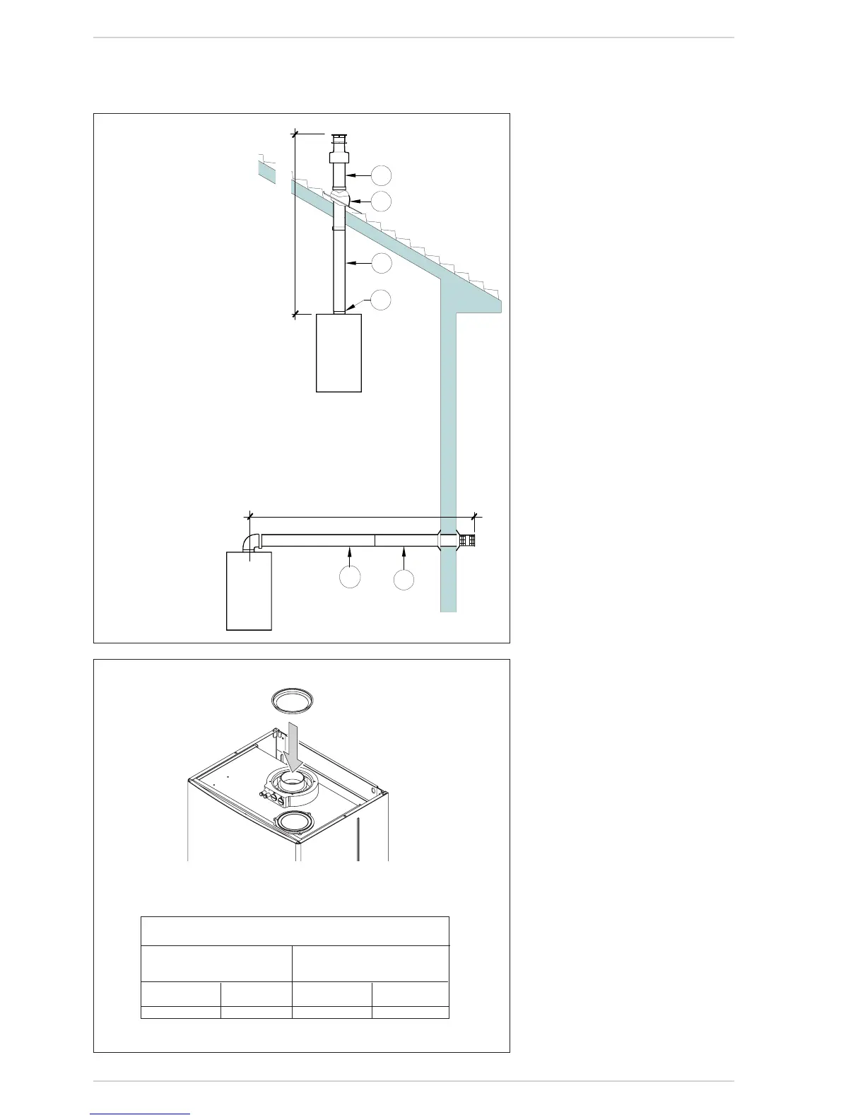
Fig.9/a
For discharge types C12, use the diaphragms ø 81.0, supplied
with the boiler, only when the length of the coaxial duct is less
than 1 metre.
For discharge types C32, use the following diaphragms according
to the length of the duct and without additional curves:
Installations with vertical Installations with vertical
extension L. 200 condensation collector
code 8086908 * code 8092803 *
Diaphragm Without Diaphragm Without
ø 81 diaphragm ø 81 diaphragm
L max = 2.5 m L max = 5 m L max = 2.5 m L max = 5 m
* Minimum length of duct L = 1.3 m.
IMPORTANT:
– Eachadditional 90°curveinstalled
reducestheavailablelengthby1.0
metres.
– Eachadditional 45°curveinstalled
reducestheavailablelengthby0.50
metres.
– The insertion of the condensation
collector (8) is obligatory for ver-
tical stretches of more than 1.3
metres.
Max3,0m
KEY
1 Roof outlet terminal L. 1284 code 8091200
2 Flashing by others
3 Extension L. 1000 code 8096103
4 Vertical adapter L. 200 code 8086908
5 Additional 90° bend code 8095801 (not shown)
Additional 45° bend code 8095900 (not shown)
6 Vertical condensation collector L. 200
code 8092803 (not shown)
7 Horizontal flue kit with terminal L. 810
code 8084811
Fig.9
Min1,3m-Max5m
Diaphragms ø 81.0
FLUE 60/100 CO-AXIAL